


5
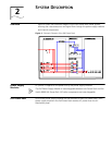
ENGINEERING, MAINTENANCE AND
TROUBLESHOOTING
Maintenance and
Troubleshooting
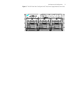
This section provides field maintenance information and troubleshooting procedures
for the PoE Power Rack and power supply modules. Review the safety information in
section 3 of this manual before performing maintenance procedures
All procedures described in this section must be performed by qualified maintenance
personnel only.
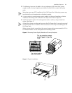
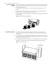
The power supply modules are not field serviceable and must be replaced in the event
of a failure.
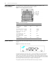
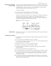
LED Indication Use Table 6 to determine if there is a fault with PoE Power Rack.
When visual indicators do not identify a defective part, notify your authorized service
representative.
Table 6 Troubleshooting Guide
Controller alarm
status
Power supply
module
display Possible problems Possible solution
RUNALM NONE ■ The AC power input
circuit breakers has
opened.
■ AC input voltage is too
low or power is lost
1 Verify that AC
power input
circuit breaker is
closed; close
circuit breaker if
it is open.
2 Verify the AC
power is present
and in normal
range.
RUNALM AC OKFAULT ■ Power supply module
failure
■ Output beyond normal
range
Replace the power
supply module
RUNALM AC OKDC
OKFAULT
Communication error
between the power supply
module and the controller
Replace the power
supply module
RUNALM AC OK ■ Power supply module has
no output and it is in
standby mode
■ Over load
■ Ambient temperature is
too high
■ Power supply module
failure;
1 Initialize the
power supply
module or reset
the controller.
2 Check if the load
is over the
rating.
3 Check the
ambient
temperature.
4 Replace the
power supply
module