


10
TRSM Installation
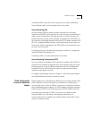
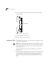
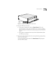
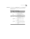
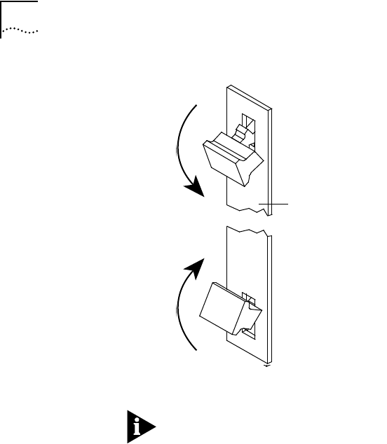
Figure 7
Handles in Inward (Inject) Position
NOTE:
Do not push the handles outside the center position or you will eject
the module. These handles act as “ejectors” when pushed outward and
“injectors” when pushed inward.
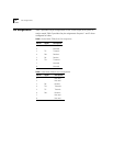
8
See the following section on “LED Activity” to verify that the TRSM has been
properly installed.
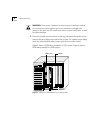
9
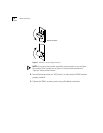
Tighten the TRSM’s securing screws using a flat-blade screwdriver.
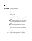
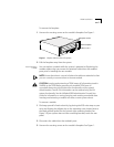
Module faceplate
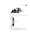
Module faceplate