


TRSM Components 13
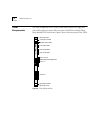
Status LEDs Each TRSM contains two Module Status LEDs and eight Port Status LEDs.
Depending on the condition, each LED is either green or yellow. Table 1
describes these LEDs.
Table 1 FDDI/Ethernet Switching Module LEDs
LEDs Name Color Description
Module
Status
Pwr/Unseat Green
Yellow
Indicates that the module is powered on
Indicates that the module is not fully
plugged into the backplane
Err
(Error)
Yellow Indicates either that an error has
occurred or that the module has failed a
diagnostic procedure
Port
Status
Port Status
1 - 8
Port Speed
1 - 8
Port Mode
1 - 2
Green
Yellow
Green
Yellow
Yellow
Green
Indicates that the associated port is active
Indicates that an error condition has
occurred with the associated port or that
the port is disabled
Indicates that the port is running at
16Mbps
Indicates that the port is running at
4Mbps
Indicates that the ports are configured as
lobes and can accept an external station
connection
Indicates that a station is attached to the
lobe port