19
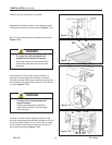
• To reduce the risk associated with
impact hazards:
− Always use appropriate supporting
means when working under the upper
drive assembly
WARNING
800rf-NA
2012 March
• To reduce the risk associated with
mechanical and electrical hazards:
− Allow only properly trained and qualifi ed
personnel to operate and/or service this
equipment
WARNING
7-INSTALLATION (continued)
(infeed conveyor attachment continued)
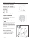
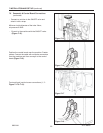
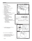
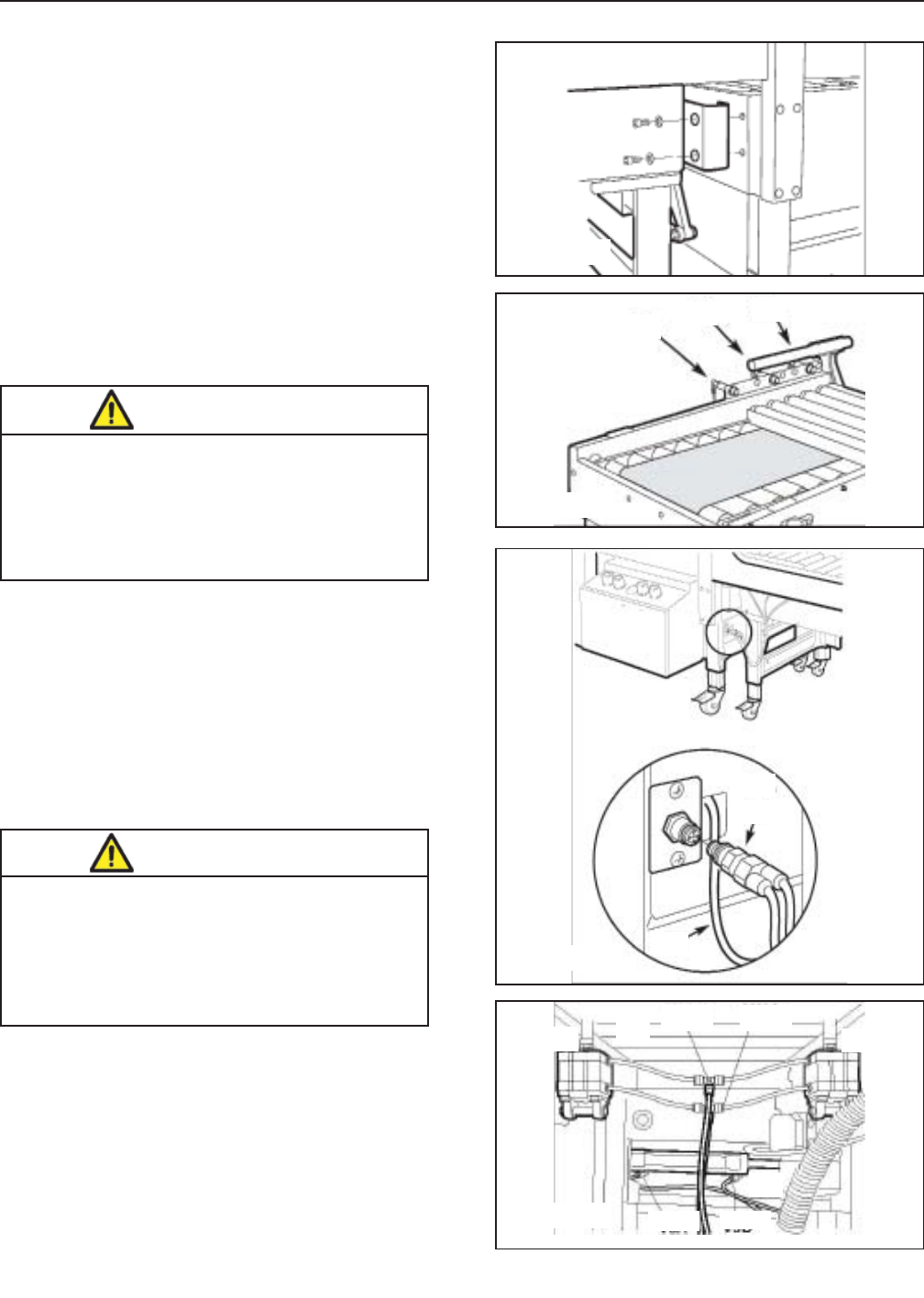
Approach the infeed conveyor to the machine and fi x
it using the screws previously removed (Figure 7-11).
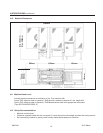
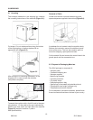
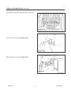
B10, B1, B2 infeed conveyor photocells connections
(Figure 7-12).
Insert the B10, B1 photocells screw connector in
the plug on the sealing machine bench as shown.
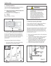
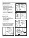
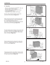
Connect the cable with screw connector deriving from
the machine to the relative B2 photocell on the infeed
conveyor (Figure 7-13).
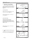
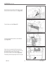
Connect air tubes from the sealing machine to the
conveyor centering guides cylinder connectors (1) and
to conveyor belt cylinders (2). Connects the air tubes
to the connectors above mentioned pay attention to
the reference numbers (Figure 7-14).
Figure 7-11
Figure 7-12
B10
B10
B1
B1
B2
B2
B2
V11AV11B
VSA VSB
1
2
2
Figure 7-13
Figure 7-14


