24
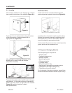
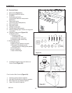
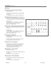
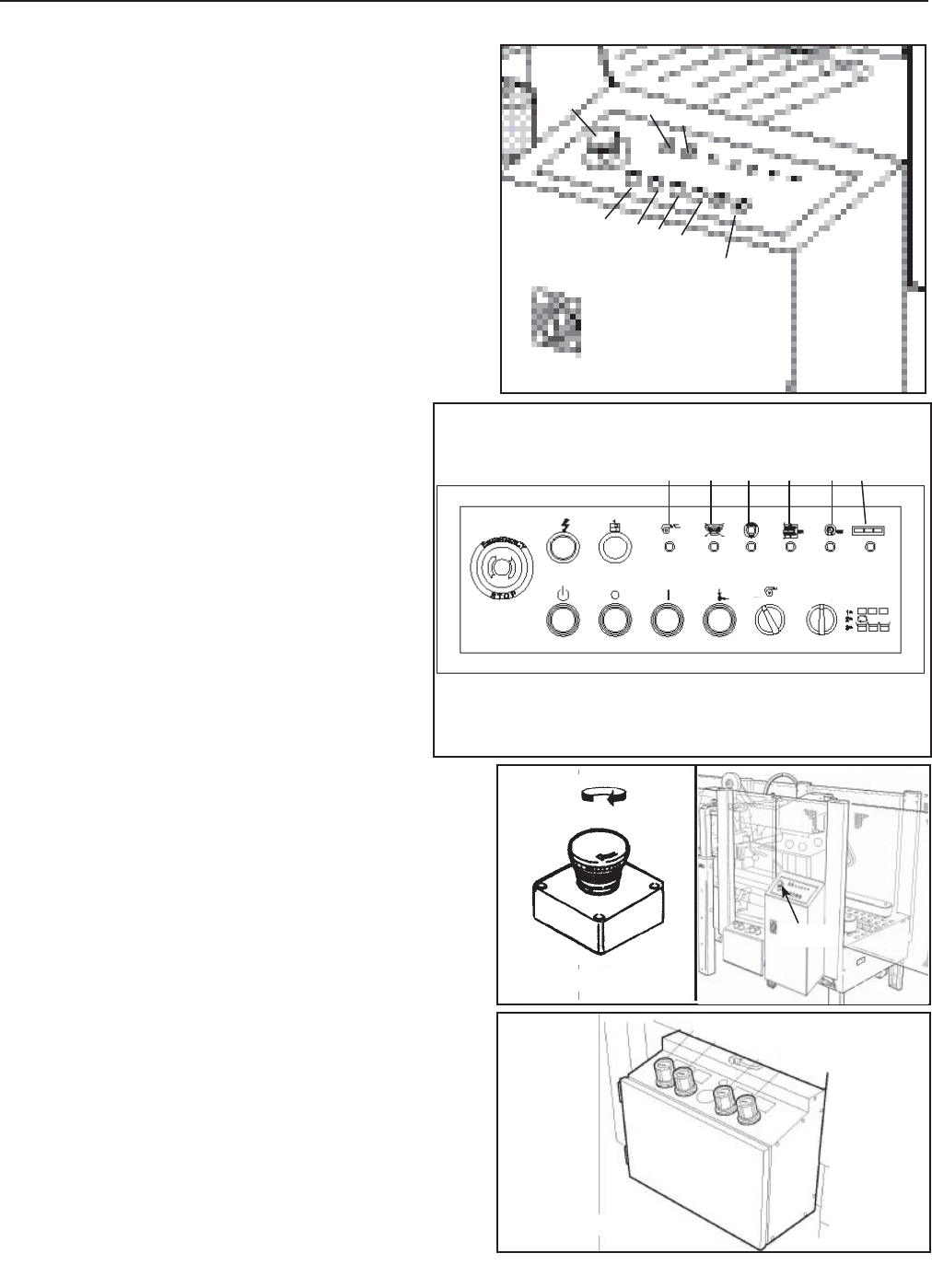
8.1 Controls Board
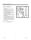
1. Main switch (Figure 8-1).
2. Emergency stop push button
(lockable)
3. Auxiliaries push button
(control board electrical components
habilitation)
4. Reset push button
(new work cycle predisposition )
5. Start push button
6. Stop push button
7. Voltage warning light
8. Thermal switch warning light
9. Warning (fl ashing light + buzzer on top guard-
not shown)
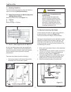
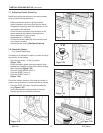
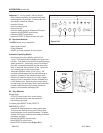
10. Operating mode panel (Figure 8-2).
a) Selector switch
1) Operating mode:
‘unchanging box size’
2) Operating mode: automatic’
3) Operating mode:‘transit only’
11. Warning lights panel
a) Cycle time out
b) Minimum gap between side belts
c) Emergency (emergency push
button pressed or safety guard opened)
d) Full sealing line
e) Low air pressure
f) Tape end/breakage
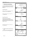
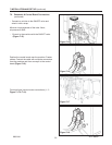
2. Lockable emergency stop push button on
Control Panel (Figure 8-3).
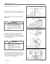
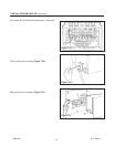
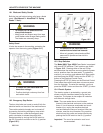
Front Junction Box Controls (Figure 8-4).
1. Centering guide pressure regulator
2. Side belts (motorizations) pressure regulator
3. Box height pick-up pressure regulator
4. Upper unit pressure regulator
8-CONTROLS
2012 March
800rf-NA
Figure 8-3
Figure 8-4
Figure 8-2
Figure 8-1
2
2
4
3
2
1
5
6
4
7
8
1
ON
OFF
3
f) e) c) b) a) d)
10
10
11
11
1
2
3
E-Stop


