


Special Set-Up Procedure (continued)
• To reduce the risk associated with
mechanical and electrical hazards:
− Turn electrical and air supply off and
disconnect before performing any
adjustments, maintenance, or servicing the
machine or taping heads
WARNING
• To reduce the risk associated with
muscle strain:
− Use the appropriate rigging and
material handling equipment when lifting or
repositioning this equipment
− Use proper body mechanics when
removing or installing taping heads that are
moderately heavy or may be considered
awkward to lift
WARNING
13-MAINTENANCE AND REPAIRS (continued)
33
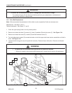
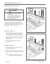
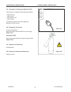
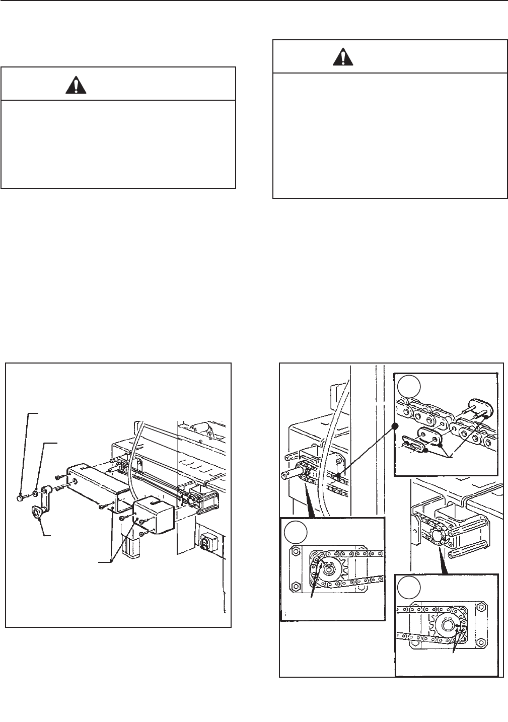
13.11.3 Chain Removal
1. Remove M6 x 16 hex hd screw, special washer
and drive belt width adjustment crank -
Figure 13-10.
2. Remove side covers (2) from each side of ma-
chine bed - Figure 13-10.
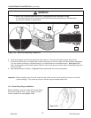
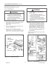
3. Remove chain. If necessary, slip width
adjustment crank on shaft and rotate until chain
master link is in convenient position for removal.
Important – Before removing chain, mark both
front and rear sprockets/chain with chalk "
or paint to be sure sprockets/chain when
re-assembled, will be in same position as
before disassembly. Figure 13-11A and
Figure 13-11B. Do not rotate sprockets
once chain is removed. (This would result
in the right and left drive assemblies not
being parallel.)
Remove chain master link and remove chain.
Figure 13-11C.
Figure 13-11 – Chain Removal
Figure 13-10 – Crank/Chain Guards
2010 December
800ab-NA
A
C
B
M6 X 16
Hex Hd Screw
Washer
Crank
Side Covers
Master
Link
Mark Chain
and Sprocket
Mark Chain
and Sprocket