


24 3M™ Multi-touch Display M2256PW User Guide
3M Touch Systems, Inc. Proprietary Information – 37531 Rev D
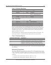
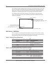
The Calibrate Extended command then positions the first calibration target inward from
the lower left corner (0,1049) and the second calibration target inward from the upper
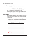
right corner (1679,0). The following illustration shows how the calibration targets are
calculated for a Windows-based system. Your operating system may be different.
The illustration below shows the coordinates of the calibration targets and display
corners. The corners show the video coordinates in parentheses and the touch screen
coordinates in brackets.
Get Feature - GetStatus
This is a request to send information that indicates the status of the controller. Among
the uses for this request are determining whether there were any power on check errors
and determining whether the last request was completed successfully.
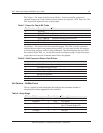
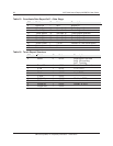
Table 5. Controller Status Setup Stage
Offset Field Size Value Description
0 bmRequestType 1 0xA1 Class,D2H,Interface
1 bRequest 1 0x01 Get Report
2 wValue 2 0x0306 msb=03=Feature
lsb=06= Feature Report ID
4 wIndex 2 0 Always 0
6 wLength 2 8 Always 8
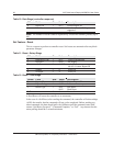
Table 6. Controller Status Data Stage (controller response)
Offset Field Size Value Description
0 Report ID 1 0x06 Feature Report ID
1 POC Status 1 0xXX Power On Check Status
2 Cmd Status 1 0xXX Status of last command
3 Touch Status 1 0 Not used
4 Async Reports 1 0xXX 0x00 = async touch output off
0x01 = async touch output on
5-7 Not used 3 0 Not used
(0, 1049) [0, 32767] (1679, 1049) [32767, 32767]
Upper Right Calibration Target
X = 1679 – (1680 x 1/8) = 1679 – 210 = 1469
Y = 0 + (1050 x 1/8) = 0 + 131 = 131
Lower Left Calibration Target
X = 0 + (1680 x 1/8) = 0 + 210 = 210
Y = 1049 - (1050 x 1/8) = 1049 - 131 = 918
(0, 0) [0, 0]
(1679, 0) [32767, 0]
(210, 918)
(1469, 131)