


38 3M™ Multi-touch Display M2256PW User Guide
3M Touch Systems, Inc. Proprietary Information – 37531 Rev D
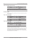
AD Indicates the PX series of controllers
F
ff
f
= Four ASCII characters that indicate the features supported by the
controller.
**** Indicates no additional features configured
Ss = Two ASCII characters that provide status information about the
controller hardware. The two characters represent one byte. Each
character is in the range 0 to 9 and A to F.
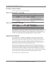
Table 2 defines the meaning of each bit in the status byte. Each bit
can be set to 1 or 0, where 1 = an error and 0 = no error. So a
response of:
00 = No diagnostic errors (normal response)
The PX running with no errors returns the following string:
<SOH> AD****00 <CR>
The format includes two bitmapped ASCII hex status bytes. A “00” indicates no errors.
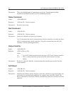
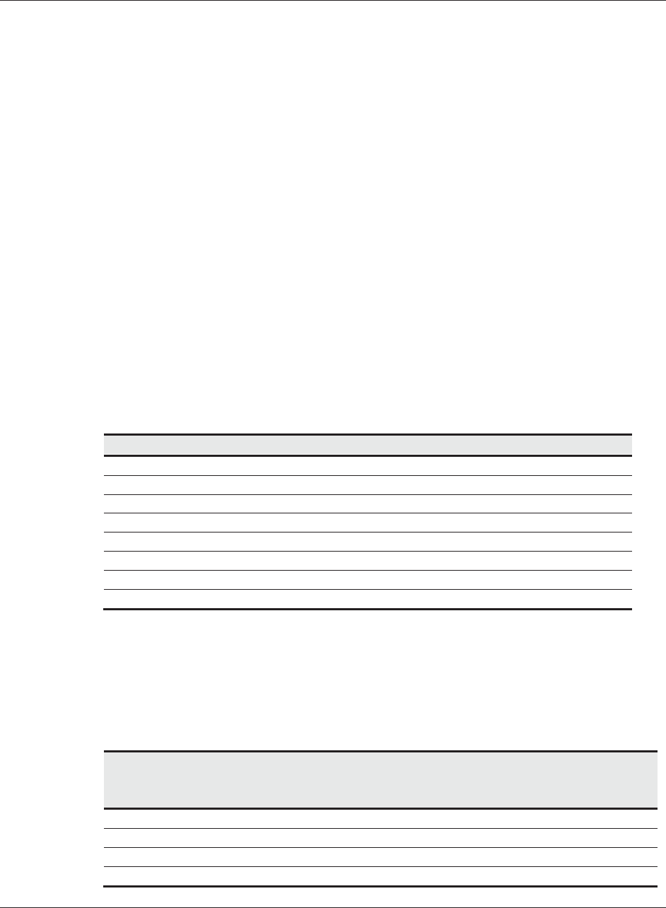
Table 19 Bit Meanings in Status Byte
Bit Description Notes
0 Not used
1 ROM_ERROR Code area checksum error
2 PWM Error Touch screen not connected or potential problem.
3 NOV_ERROR Parameter Block1 checksum error
4 HDW_ERROR Problem with ADCs
5 Not used
6 Not used
7 Not used
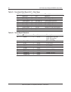
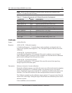
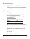
Touch Data Format
The format is a six byte packet that includes one status byte, four bytes of binary X,Y
position data and a touch ID. The X,Y coordinates are 14 bits, providing a range of 0 to
16,383. The data is sent in the following format:
Table 20 Touch Data Format Settings
Data Sequence Bits
7 6 5 4 3 2 1 0
Status - Byte 1 1 P
1
0 0 0 0 0 0
X - Byte 2 0 X6 X5 X4 X3 X2 X1 X0
X - Byte 3 0 X13 X12 X11 X10 X9 X8 X7
Y - Byte 4 0 Y6 Y5 Y4 Y3 Y2 Y1 Y0