


8e6 ThreaT analysis reporTer Quick sTarT Guide 11
Rack Mount the “H” Server
Rack Mount Instructions
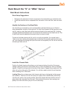
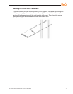
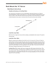
Identify the Sections of the Rack Rails
You should have received two rack rail assemblies with the 8e6 server unit. Each of
these assemblies consists of two sections: An inner xed chassis rail that secures to the
unit (A), and an outer xed rack rail that secures directly to the rack itself (B). Two pairs
of short brackets to be used on the front side of the outer rails are also included.
Install the Inner Rails
Both the left and right side inner rails have been pre-attached to the chassis. Proceed to
the next step.
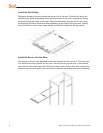
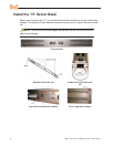
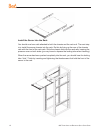
Install the Outer Rails
Begin by measuring the distance from the front rail to the rear rail of the rack. Attach a
short bracket to the front side of the right outer rail and a long bracket to the rear side of
the right outer rail. Adjust both the short and long brackets to the proper distance so that
the rail can t snugly into the rack. Secure the short bracket to the front side of the outer
rail with two M4 screws and the long bracket to the rear side of the outer rail with three
M4 screws. Repeat these steps for the left outer rail.
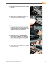
Locking Tabs: Both chassis rails have a locking tab, which serves two functions. The
rst is to lock the server into place when installed and pushed fully into the rack, which is
its normal position. Secondly, these tabs also lock the server in place when fully extend-
ed from the rack. This prevents the server from coming completely out of the rack when
you pull it out for servicing.