


8e6 ThreaT analysis reporTer Quick sTarT Guide 5
Rack Mount the “S” or “MSA” Server
Rack Mount Instructions
Rack Setup Suggestions
Determine the placement of each component in the rack before you install the rails.
Install the heaviest server components on the bottom of the rack rst, and then work
up.
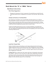
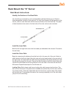
Identify the Sections of the Rack Rails
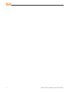
You should have received two rack rail assemblies with the 8e6 server unit. Each of
these assemblies consists of two sections: An inner xed chassis rail that secures to the
unit (A), and an outer xed rack rail that secures directly to the rack itself (B). A sliding
rail guide sandwiched between the two should remain attached to the xed rack rail. The
A and B rails must be detached from each other in order to install.
To remove the xed chassis rail (A), pull it out as far as possible. You should hear a
“click” sound as a locking tab emerges from inside the rail assembly and locks the inner
rail. Then depress the locking tab to pull the inner rail completely out. Do this for both the
left and right side rack rail.
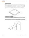
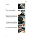
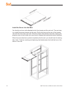
Install the Chassis Rails
Position the xed chassis rail sections you just removed along the side of the server
chassis making sure the ve screw holes line up. Note that these two rails are left/right
specic. Screw the rail securely to the side of the chassis. Repeat this procedure for the
other rail on the other side of the chassis. You will also need to attach the rail brackets
when installing into a Telco rack.
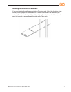
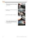
Locking Tabs: As you have seen, both chassis rails have a locking tab, which serves
two functions. The rst is to lock the server into place when installed and pushed fully
into the rack, which is its normal position. Secondly, these tabs also lock the server in
place when fully extended from the rack. This prevents the server from coming com-
pletely out of the rack when you pull it out for servicing.
•
•