


Hardware Setup 2-9
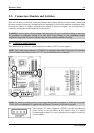
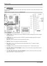
2-5. Connectors, Headers and Switches
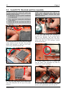
Here we will show you all of the connectors, headers and switches, and how to connect them. Please read
the entire section for necessary information before attempting to finish all the hardware installation inside
the computer chassis. A complete enlarged layout diagram is shown in Chapter 1 for all the position of
connectors and headers on the board that you may refer to.
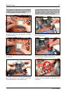
WARNING: Always power off the computer and unplug the AC power cord before adding or removing
any peripheral or component. Failing to so may cause severe damage to your motherboard and/or
peripherals. Plug in the AC power cord only after you have carefully checked everything.
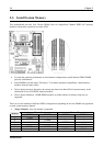
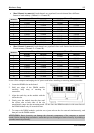
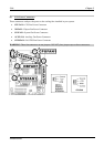
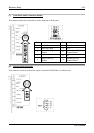
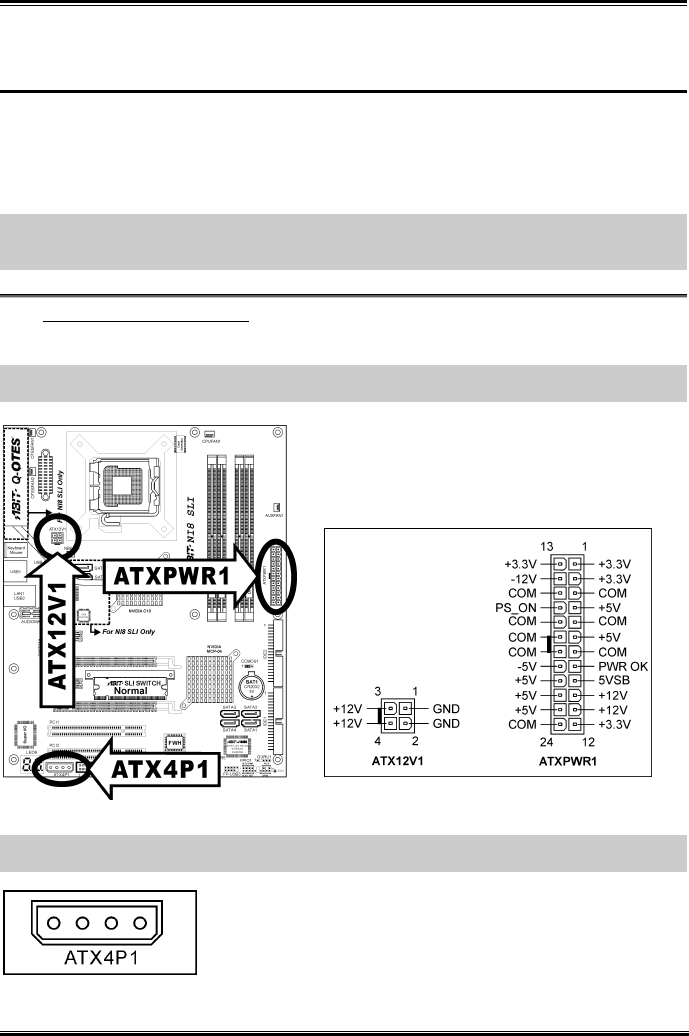
(1). ATX Power Input Connectors
This motherboard provides two power connectors to connect ATX12V power supplier.
NOTE: This 24-pin power connector “ATXPWR1” is compliant to the former 20-pin type. Pay attention
to the orientation when doing so (Pin-11, 12, 23, and 24 should be left un-connected).
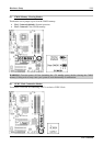
NOTE: For a heavily loaded system, a power supply that provides a minimum of 350W and 20A on the
+5VDC rail is recommended. To support wake-up features, 2A on the +5VSB rail is required.
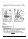
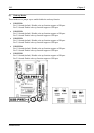
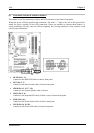
The auxiliary 12V power connector [ATX4P1] provides an additional
power source for devices added on PCI Express slots. It is highly
recommended to attach 12V power from the power supplier for the best
system stability.
User’s Manual