


Programming Example (C)
The following program fragment in C language illustrates the foregoing:
const BASE_ADDRESS 0x300;
outportb(BASE_ADDRESS +3, 0x89); /*This instruction sets the mode to Mode 0, ports A and
B as output, and port C as input. Since bit D7 is high, the
output buffers are set to tristate condition. See item b.
above.*/
outportb(BASE_ADDRESS,0);
outportb(BASE_ADDRESS+1,0); /*These instructions set the initial state of ports A and B
to all zeroes. Port C is not set because it is configured as
an input. See item c. above.*/
outportb(BASE_ADDRESS +3, 0x09); /*Enable the tristate output buffers by using the same
control byte used to configure the PPI, but now set bit
D7 low. See item d. above.*/
Programming Example (Basic)
The following example in BASIC is provided as a guide to assist you in developing your working software.
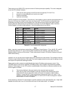
In this example, the card base address is 2D0 hex and the I/O lines of group 0 are to be setup as follows:
Port A = Input
Port B = Output
Port C Hi = Input
Port C Lo = Output
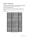
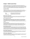
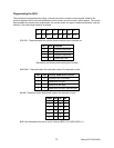
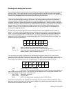
The first step is to configure the control register. Configure bits of the control register as:
D7 1 Active Mode Set
D6 0 Mode 0
D5 0 Mode 0
D4 1 Port A = input
D3 1 Port C Hi = input
D2 0 Mode 0
D1 0 Port B = output
D0 0 Port C Lo -= output
This corresponds to 98 hex. If the card address is 2D0 hex, use the BASIC OUT command to write to the
control register as follows:
10 BASEADDR=&H2D0
20 OUT BASEADDR+3,&H98
To read the inputs at Port A and the upper nybble of Port C:
30 X=INP(BASEADDR)'Read Port A
40 Y=INP(BASEADDR+2)/16'Read Port C Hi
To set outputs high (1) at Port B and the lower nybble of Port C:
50 OUT BASEADDR+1,&HFF'Turn on all Port B bits
60 OUT BASEADDR+2,&HF'Turn on all bits of Port C lower nybble
Manual PCI-DIO-24DH
19