


Reading and Loading the Counters
If you attempt to read the counters on the fly when there is a high input frequency, you will most likely get
erroneous data. This is partly caused by carries rippling through the counter during the read operation.
Also, the low and high bytes are read sequentially rather than simultaneously and, thus, it is possible that
carries will be propagated from the low to the high byte during the read cycle.
To circumvent these problems, you can perform a counter-latch operation in advance of the read cycle.
To do this, load the RW1 and RW2 bits with zeroes. This instantly latches the count of the selected
counter (selected via the SC1 and SC0 bits) in a 16-bit hold register. (An alternative method of latching
counter(s) that has an additional advantage of operating simultaneously on several counters is through a
readback command to be discussed later.) A subsequent read operation on the selected counter returns
the held value. Latching is the best way to read a counter on the fly without disturbing the counting
process. You can only rely on directly read counter data if the counting process is suspended while
reading by bringing the gate low.
For each counter you must specify in advance the type of read or write operation that you intend to
perform. You have a choice of loading/reading (a) the high byte of the count, or (b) the low byte of the
count, or (c) the low byte followed by the high byte. This last is most generally used and is selected for
each counter by setting the RW1 and RW0 bits to ones. Subsequent read/load operations must be
performed in pairs in this sequence or the sequencing flip-flop in the 8254 chip will get out of step. The
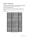
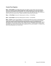
readback command byte format is:
B7 B6 B5 B4 B3 B2 B1 B0
1 1 CNT STA C2 C1 C0 0
CNT: When 0, latches the counters selected by bits C0-C2.
STA: When 0, returns the status byte of counters selected by C0-C2.
C0, C1, C2: When high, select a particular counter for readback. C0 selects Counter 0, C1
selects Counter 1, and C2 selects Counter 2.
You can perform two types of operations with the readback command. When CNT=0, the counters
selected by C2 through C0 are latched simultaneously. When STA=0, the counter status byte is read
when the counter I/O location is accessed. The counter status byte provides information about the current
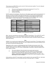
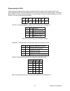
output state of the selected counter and its configuration. The status byte returned if STA=0 is:
B7 B6 B5 B4 B3 B2 B1 B0
OUT NC RW1 RW2 M2 M1 M0 BCD
OUT: Current state of counter output pin.
NC: Null count. This indicates when the last count loaded into the counter register has
been loaded into the actual counter. The exact time of load depends on the configuration selected. Until
the count is loaded into the counter, it cannot be read.
RW1, RW0: Read/Write command.
M2, M1, M0: Counter mode.
BCD: BCD = 0 is binary mode, otherwise counter is in BCD mode.
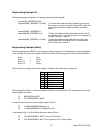
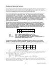
If both STA and CNT bits in the readback command byte are set low and the RW1 and RW0 bits have
both been previously set high in the counter control register (thus selecting two-byte reads), then reading
a selected counter address location will yield:
Manual PCI-DIO-24DH
24