


Chapter 3 47
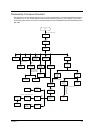
Disassembly Procedure Flowchart
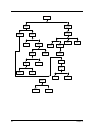
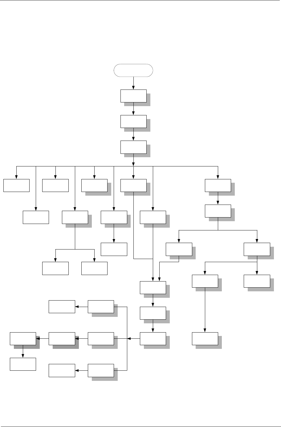
The flowchart on the succeeding page gives you a graphic representation on the entire disassembly sequence
and instructs you on the components that need to be removed during servicing. For example, if you want to
remove the system board, you must first remove the keyboard, then disassemble the inside assembly frame in
that order.
Start
Base Cover
x7 (fix on base cover)
Battery
Dommy Cover
Dx4
Cx1
Battery
MDC Modem
Card
Optical Drive
Module
(Please see
next page)
Subwoofer
Memory
HDD Module
Thermal
Module (FAN
Sink) w/
screws *4pcs
CPU
VGA Card
(AGP Card)
Wireless Card
Inverter Cover
Cx2
x2
Disconnect
subwoofer cable
Cx2
Cx4
Cx1 Cx4
Cx3
Hinge Cover
Jx4
Upper System
Cover (Middle
Cover)
Keyboard
x6
x4 on rear
Disconnect LED cable
x4
LCD Module
Silicon Line Pad
(LCD Decoration
Bar)
LCD Skirting
Board (LCD
Bezel)
LCD Outer
Shield (LCD
panel)
LCD
Wireless
Antenna
Dx8
Bx2
Bx4
Side Brackets
(LCD
Brackets)
Inverter Board
LED Cable
Ux8
Inverter Board
Brackets
LCD Cable
x2
Remove inverter board mylar
LED Cable
Ox4
LED Board
(Launch
Board)
Disconnect touchpad FFC
Px1
Qx2
Kx5
Mx2
Tx6
Jx4
Dx8
See Next
Page
Disconnect HDD
power cable and
IDE coaxial cable
Rx4
HDD Bracket HDD
Dx6
x4