


Chapter 3 45
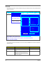
Disassembly Procedure Flowchart
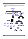
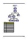
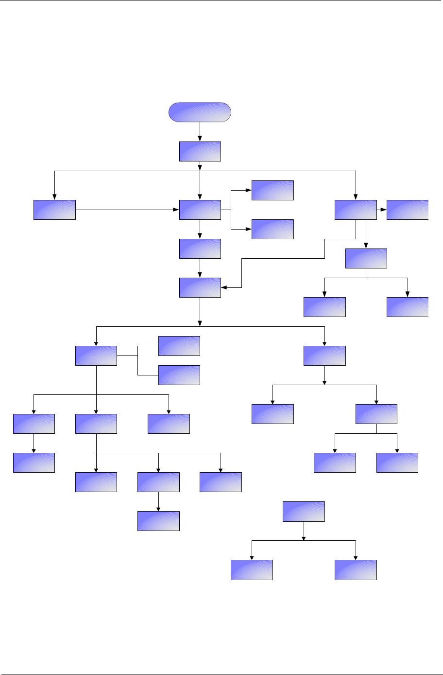
The flowchart on the succeeding page gives you a graphic representation on the entire disassembly sequence
and instructs you on the components that need to be removed during servicing. For example, if you want to
remove the system board, you must first remove the keyboard, then disassemble the inside assembly frame in
that order.
Start
Battery
Middle Cover
DIMM/HDD
Cover
Wireless LAN
Cover
*2
I*4
*2
*1
HDD Module
*4
*3
CPU
Fan
Lower Case
Assembly
*2
VGA Heatsink Modem Board
Wireless LAN
Cover
ODD Module
Memory
HDDHDD Bracket
*4
Keyboard
LCD Module
*4
*1
*13
Upper Case
Assembly
*3
Upper Case
Touchpad
Assembly
Touchpad
Bracket
Touchpad
Lower Case
Main Board
Assembly
Speaker Set
CPU Heatsink
*3*6
RTC Battery
Bluetooth
Module
ODD Module
*2
ODD ODD Bracket