


58 Chapter 3
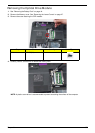
Main Unit Disassembly Process
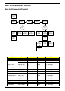
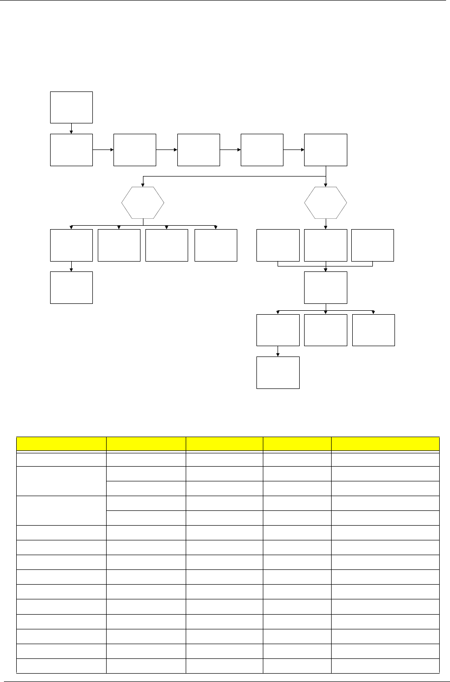
Main Unit Disassembly Flowchart
Screw List
Step Screw Quantity Color Part No.
Switch Cover M2*3 (NL) 2 Black 86.AR102.004
LCD Module M2.5*8(NL) 4 Black 86.AR102.001
M2.5*5 (NL) 2 Black 86.AR102.002
Upper Cover M2.5*8 (NL) 8 Black 86.AR102.001
M2.5*5 (NL) 7 Black 86.AR102.002
Touch Pad Bracket M2*3 (NL) 2 Black 86.AR102.004
Launch Board M2*3 (NL) 2 Black 86.AR102.004
Speaker M2*3 (NL) 4 Black 86.AR102.004
I/O Board M2.5*5 (NL) 1 Black 86.AR102.002
Bluetooth Board M2*3 (NL) 1 Black 86.AR102.004
Modem Module M2*3 (NL) 2 Black 86.AR102.004
Mainboard M2.5*5 (NL) 1 Black 86.AR102.002
Thermal Module M2.5*6.5 4 Black 86.AR102.012
CPU Fan M2*4-NI (NL) 3 Black 86.AR102.006
HDMI Module M2*4-NI (NL) 2 Black 86.AR102.006
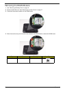
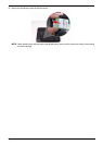
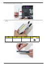
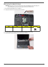
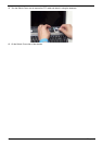
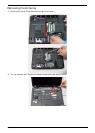
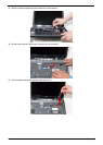
Remove
Switch Cover
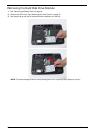
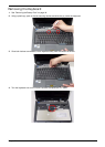
Remove
Keyboard
Remove External
Modules before
proceeding
Remove
Antenna
Remove
LCD Module
Remove
Upper Cover
Remove
Touchpad
Bracket
Remove
I/O Board
Remove
Launch Board
Remove
Finger Print
Reader
Remove
Speaker Module
Remove
Modem Board
Remove
Thermal Module
Remove
CPU
Remove
Switch Board
Remove
Mainboard
Remove
Bluetooth Board
Upper
Cover
Lower
Cover
Remove
CPU Fan
Remove
HDMI Module