


Chapter 3 79
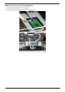
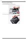
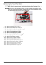
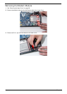
Removing the Touch Pad Board
IMPORTANT:The Touch Pad board is integrated into the design of the Upper Cover. To replace the Touch Pad
board, remove all components from the Upper Cover and install an entirely new Upper Cover.
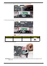
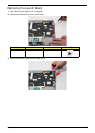
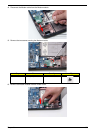
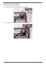
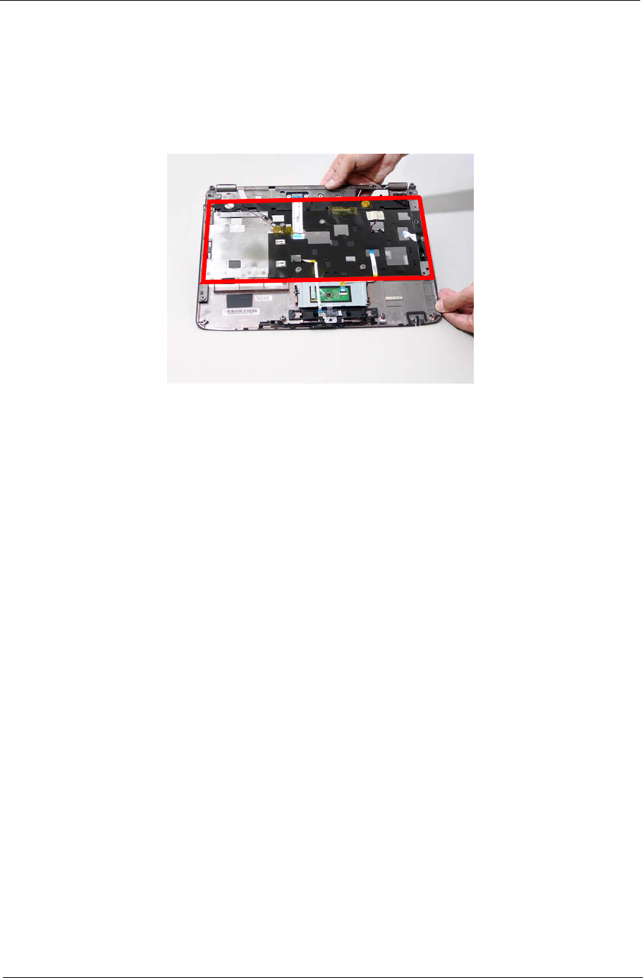
IMPORTANT:The MOSFET pad is attached to the Upper Cover and is reusable. If the replacement Upper
Cover does not have a MOSFET pad (see highlighted area below), remove the MOSFET pad from
the replaced Upper Cover and stick it to the new Upper Cover.
1. See “Removing the Battery Pack” on page 44.
2. See “Removing the SD dummy card” on page 45.
3. See “Removing the ExpressCard dummy card” on page 46.
4. See “Removing the Lower Covers” on page 47.
5. See “Removing the DIMM Modules” on page 49.
6. See “Removing the WLAN Module” on page 50.
7. See “Removing the Hard Disk Drive Module” on page 52.
8. See “Removing the Optical Drive Module” on page 55.
9. See “Removing the Keyboard” on page 61.
10. See “Removing the LCD Module” on page 66.
11. See “Removing the Upper Cover” on page 68.
12. See “Removing the Touch Pad Bracket” on page 72.
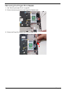
13. See “Removing the Finger Print Reader” on page 74.
14. See “Removing the Launch Board” on page 75.
15. See “Removing the Speaker Module” on page 76.
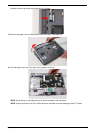
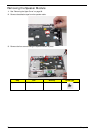
16. See “Removing the Switch Board” on page 78.