


78 Chapter 3
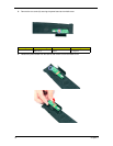
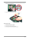
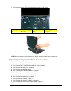
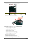
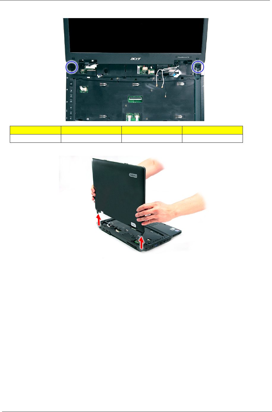
11. Remove the two screws (D) from the left and right hinge of the LCD module.
12. Carefully remove the LCD module from the base unit.
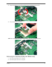
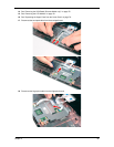
NOTE: When connecting the cable back to the unit, please note that the cable should be routed well.
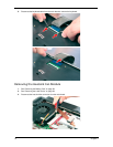
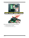
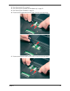
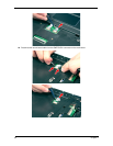
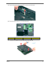
Separating the Upper Case from the Lower Case
1. See “Removing the Battery Pack” on page 56.
2. See “Removing the SD dummy card” on page 57.
3. See “Removing the PC and ExpressCard dummy cards” on page 58.
4. See “Removing the Lower Cover” on page 59.
5. See “Removing the DIMM” on page 60.
6. See “Removing the WLAN Board Modules” on page 61.
7. See “Removing the Hard Disk Drive Module” on page 63.
8. See “Removing the Optical Drive Module” on page 64.
9. See “Removing the Middle Cover” on page 68.
10. See “Removing the Keyboard” on page 71.
11. See “Removing the Heatsink Fan Module” on page 72.
12. See “Removing the CPU and VGA Heatsink Module” on page 73.
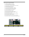
Step Size (Quantity) Color Torque
1~2 M2 x L8 (2) Black 4.0 kgf-cm