


Chapter 3 63
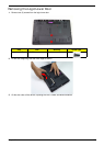
Main Unit Disassembly Process
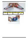
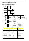
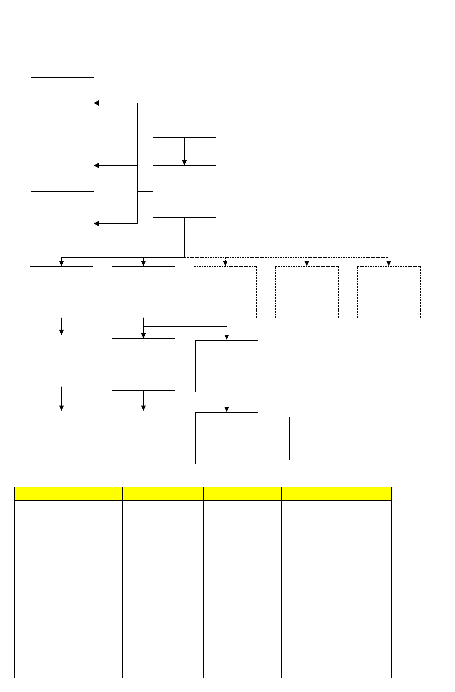
Main Unit Disassembly Flowchart
Screw List
Step Screw Quantity Part No.
Lower Cover M2.5*8 12 86.R4F02.002
M2*3 4 86.R4F02.007
Upper Cover M2.5*5 7 86.R4F02.001
Power Board M2*3 2 86.R4F02.007
Card Reader M2*3 1 86.R4F02.007
USB Board M2*3 1 86.R4F02.007
Mainboard M2.5*5 1 86.R4F02.001
Mainboard (UMA only) M2.5*5 3 86.R4F02.001
Thermal Module M1.98*3 4 86.R4F02.004
Thermal Module
(Discrete only)
M2.5*5 2 86.R4F02.001
LCD Module M2.5*8 4 86.R4F02.002
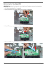
Remove
Mainboard
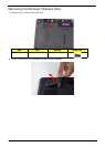
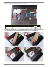
Remove
Upper Cover
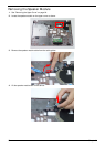
Remove
Power Board
Remove External
Modules before
proceeding
Remove
Touchpad FFC
Remove
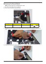
Speaker Module
Remove
CPU
Remove
Thermal Module
Remove
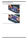
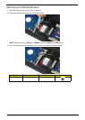
Bluetooth Module
Remove
Card Reader
Board
(Discrete Only)
Remove
USB Board
Remove
DC-IN Assembly
Remove
LCD Module
Remove
ODD Connector
Board
(UMA Only)
Remove
Bluetooth Module
Remove
USB Board
Discrete Flowchart
UMA Flowchart