


64 Chapter 3
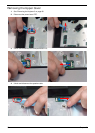
Main Unit Disassembly Process
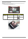
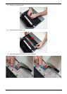
IMPORTANT: Cable paths and positioning may not represent the actual model. During the removal and
replacement of components, ensure all available cable channels and clips are used and that the cables are
replaced in the same position.
NOTE: The product previews seen in the disassembly procedures may not represent the final product color or
configuration.
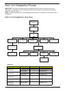
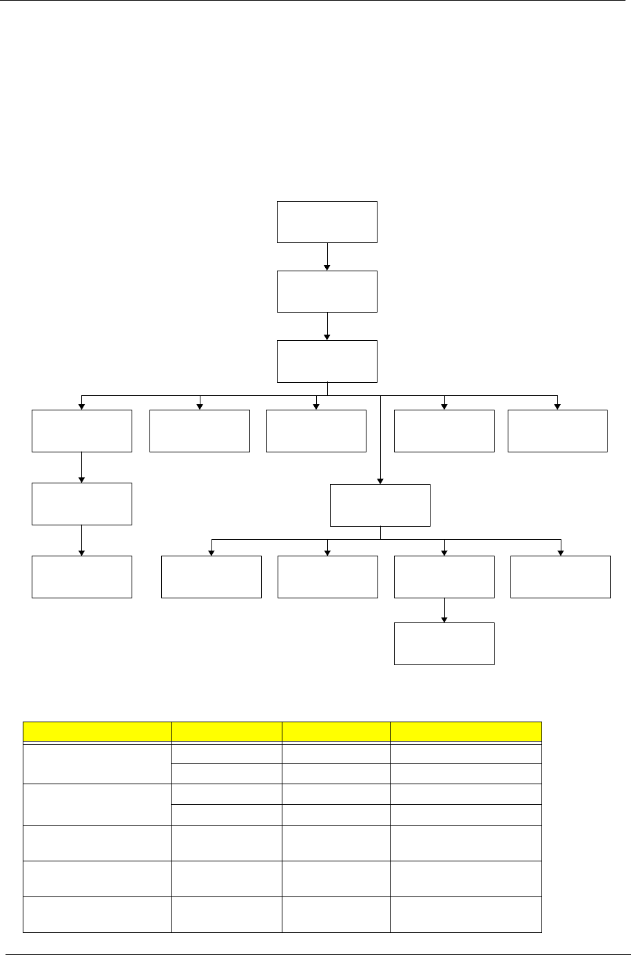
Main Unit Disassembly Flowchart
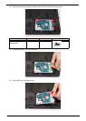
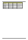
Screw List
Step Screw Quantity Part No.
Upper Cover
Disassembly
M2.5*4L(BNI) 6 86.T23V7.009
M2.0*3L(BK) 1 86.ARE07.002
Lower Cover
Disassembly
M2.5*6L(BNI) 22 86.A08V7.004
M2.5*2L(NI) 2 86.EDM07.002
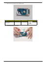
Switch Board
Disassembly
M2.5*2L(NI) 2 86.EDM07.002
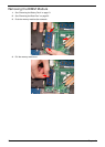
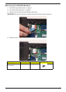
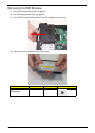
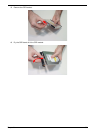
Power Module
Disassembly
M2.0*3L(BK) 3 86.ARE07.002
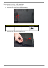
USB board
Disassembly
M2.5*6L(BNI) 1 86.A08V7.004
Remove external
modules before
proceeding
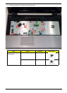
Remove keyboard
Remove upper cover
Remove Power BoardRemove Switch Board
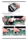
Remove main board
Remove thermal
module
Remove LAN Board
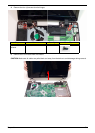
Remove LCD module
Remove CRT Cable
Remove DC cable
Remove USB Board
Remove Bluetooth
Module
Remove CPU
Remove RTC Battery
Remove PCH
Heatsink