


Chapter 3 89
LCD Module Disassembly Process
IMPORTANT: Cable paths and positioning may not represent the actual model. During the removal and
replacement of components, ensure all available cable channels and clips are used and that the cables are
replaced in the same position.
NOTE: The product previews seen in the disassembly procedures may not represent the final product color or
configuration.
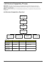
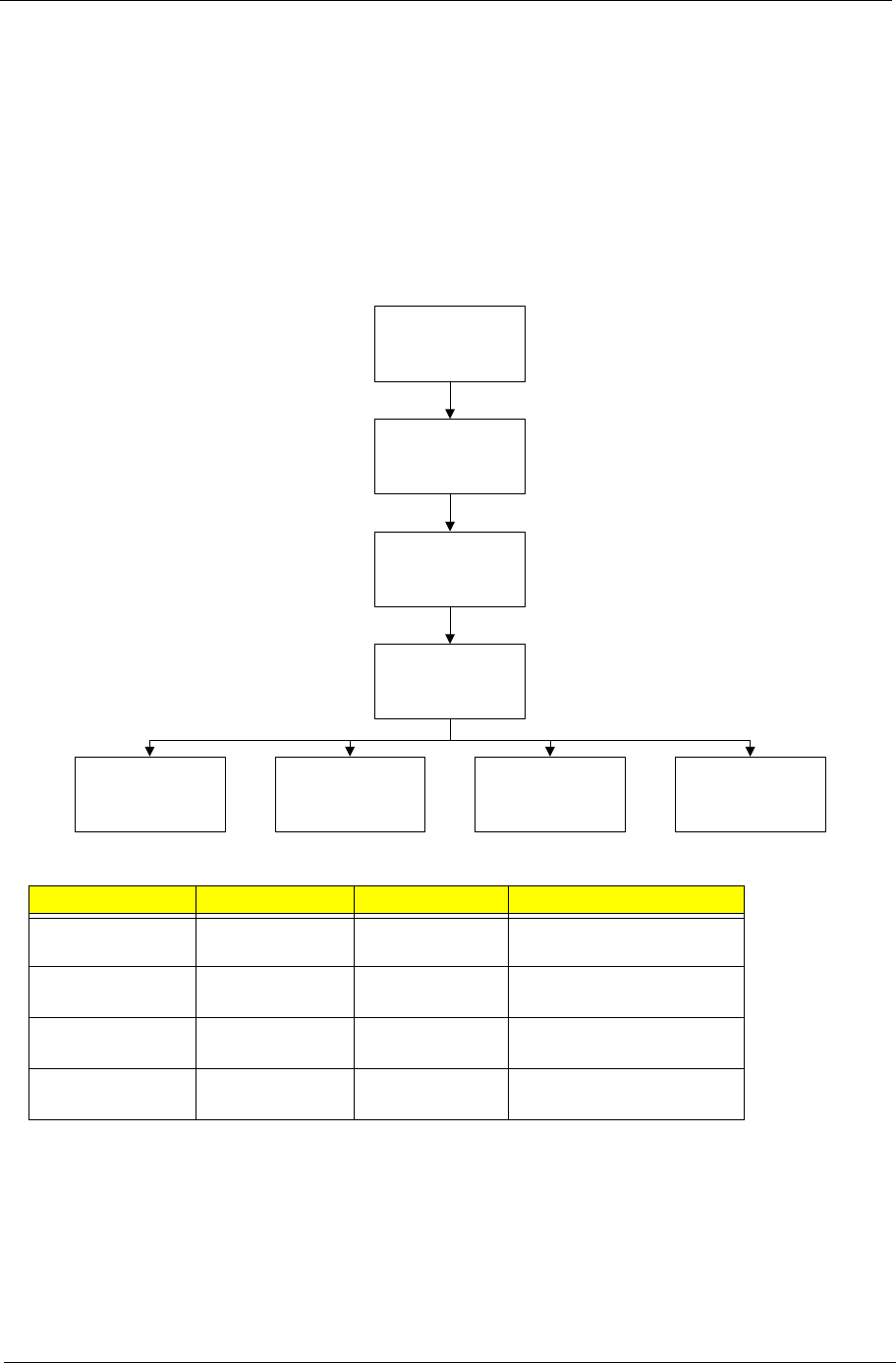
LCD Module Disassembly Flowchart
Screw List
Step Screw Quantity Part No.
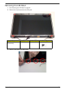
LCD Bezel
Disassembly
M2.5*6L(BNI) 2 86.A08V7.004
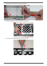
LCD Panel
Disassembly
M2.0*3L(BK) 6 86.ARE07.002
Left Hinge
Disassembly
M2.5*5L(NI) 3 TBD
Right Hinge
Disassembly
M2.5*5L(NI) 3
Remove LCD panel
from main unit before
proceeding
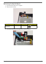
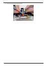
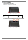
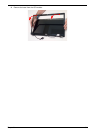
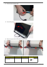
Remove LCD bezel
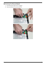
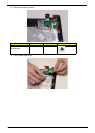
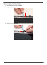
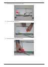
Remove camera
module
Remove LCD panel
Remove LCD bracketsRemove LVDS cable
Remove WLAN
antennas
Remove microphone