


Chapter 3 83
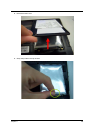
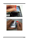
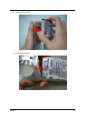
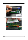
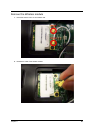
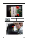
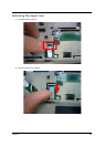
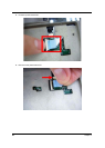
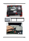
LCD Module Disassembly Process
IMPORTANT: Cable paths and positioning may not represent the actual model. During the removal and
replacement of components, ensure all available cable channels and clips are used and that the
cables are replaced in the same position.
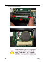
NOTE: The product previews seen in the disassembly procedures may not represent the final product color or
configuration.
1.
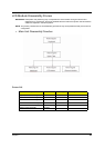
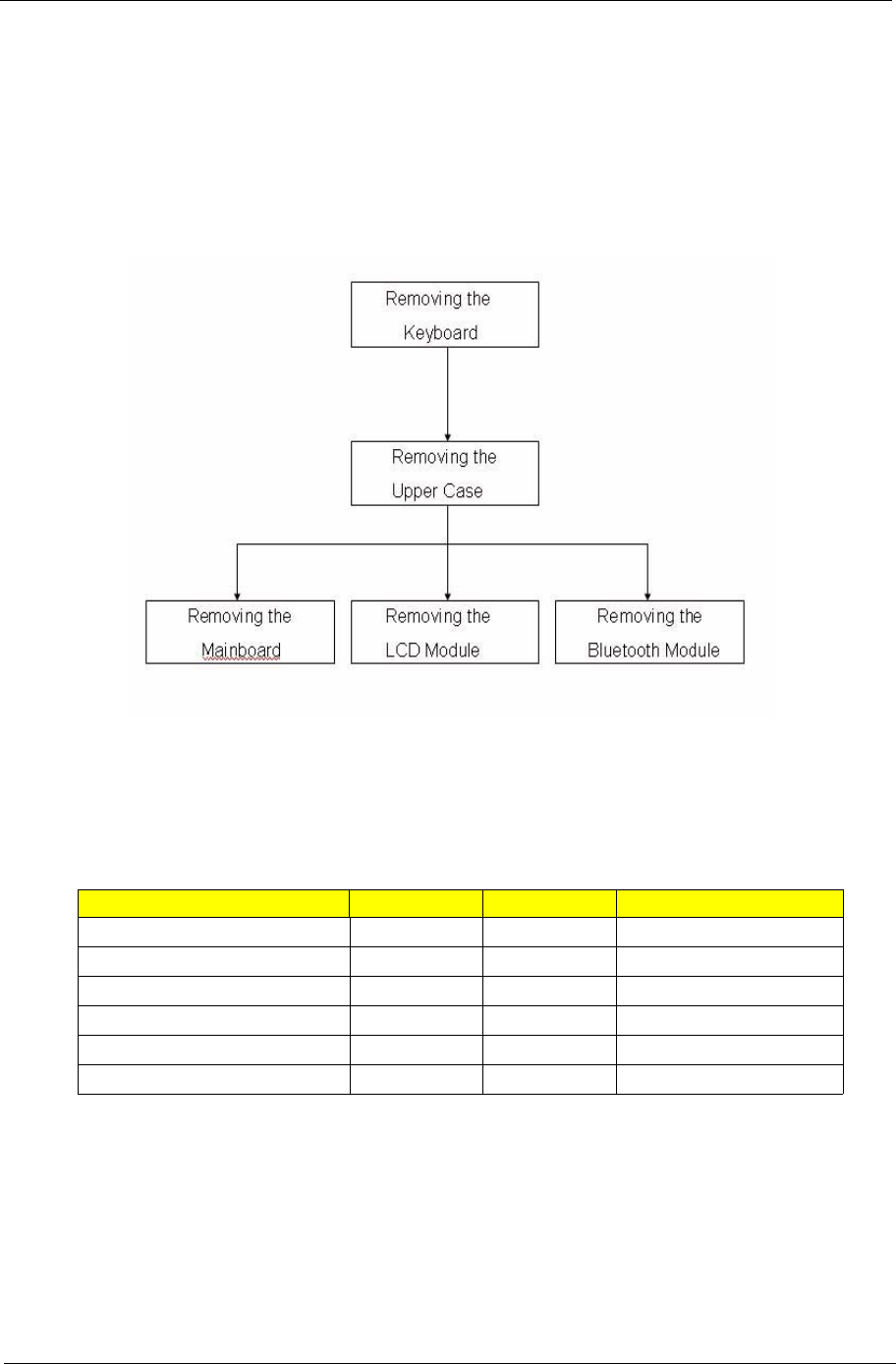
Main Unit Disassembly Flowchar.
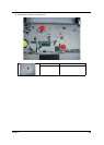
Screw List
Step Screw Quantity part no
Upper Cover Disassembly M2.5*6L 2
Lower Cover Disassembly M2*6L 9
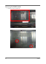
LCD Module Disassembly M2.5*4L 2
Power bracket Disassembly M2*3L 1
Mainboard Disassembly M2*3L 4
Mainboard Disassembly M2.5*4L 4