


Installation
Manual No. 775051 2-5
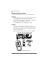
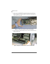
Connectors, Jumpers and LEDs
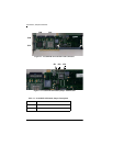
There are two external Ultra 160 SCSI channels (connectors) supported on
the controller as shown in Figure 2-1.
SCSI jumpers should normally be set to their default settings, no adjustments
are needed. Default jumper locations are shown in Figure 2-2 and are
described in Table 2-1.
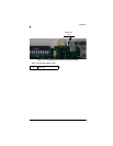
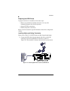
The AcceleRAID 352 controller has one LED on the front side as shown in
Figure 2-3 and described in Table 2-2.
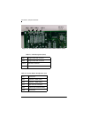
There are four LEDs on the back of the controller that are mode indicators
while the controller is running, shown in Figure 2-4 and described in Table
2-3.
The LEDs indicate single ended, LVD, and FAIL modes.
In addition there is a six-pin header. Figure 2-4 identifies the location of each
pin. Table 2-4 identifies the function of each pin: 3.3V power, Channel 0
and Channel 1 SCSI activity, cache dirty status and, a ground pin.
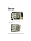
When you have checked the termination requirements, completed the
connections of your desired SCSI devices and other possible devices such as
a CD-ROM drive or a tape drive, close your system with the cover.
PCI Hotplug
☛ Note
Please see Appendix D for information on how to
implement the Hotplug feature for your system’s
requirements.