


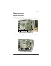

Connectors, Jumpers and LEDs
2-8 AcceleRAID 352 Installation Guide
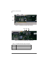
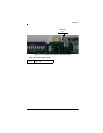
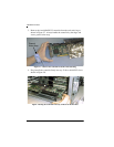
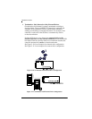
Figure 2-4. AcceleRAID 352 Controller with LEDs and Pin Numbers (back)
Table 2-3. LED Descriptions (back)
SE 1 Single-ended LED, Channel 1
SE 0 Single-ended LED, Channel 0
LVD 0 LVD LED, Channel 0
LVD 1 LVD LED, Channel 1
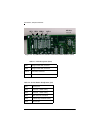
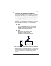
Table 2-4. Six-Pin Header Identification (JP3)
Pin 1 3.3V power
Pin 2 Channel 0 SCSI activity
Pin 3 Channel 1 SCSI activity
Pin 4 Not used, not connected
Pin 5 Cache Dirty and SCSI activity
Pin 6 Ground pin
SE 1 SE 0 LVD 0 LVD 1
PIN Nos.
6 5 4 3 2 1