


Chapter 5 92
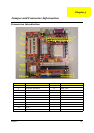
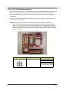
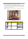
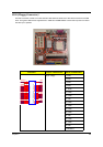
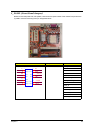
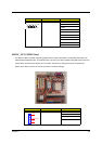
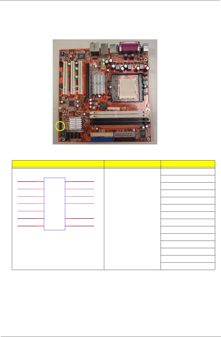
F_PANEL (Front Panel Jumper)
Please connect the power LED, PC speaker, reset switch and power switch of the chassis front panel to the
F_PANEL connector according to the pin assignment below.
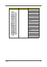
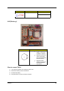
Illustration Jumper / Header Name Pin No. and definition
Front Panel Header 1: FP_1
2: LEDP
3: P1
4: PMSLED
5: GND
6: SWITCH_ON*
7: FP_RESET*_FP
8: GND
9: FP_9
10: KEY
11: 3D3V_SYS
12: 3D3V_DUAL
13: P2
14: LED_TX
FP_1
FP_RESET*_FP
P2
FP_9
LEDP
Orange
1
Orange
3
Blue
5
Blue
7
Black
9
Orange
11
Green
2
Red
6
Red
8
Green
12
Green
14
Green
4
Orange
13
SWITCH_ON*
P1
PMSLED
GN D
GN D
+3.3 V_Dua l
LED_TX
+3.3 V_SY S