


Chapter 3 49
Disassembly Procedure Flowchart
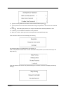
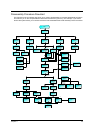
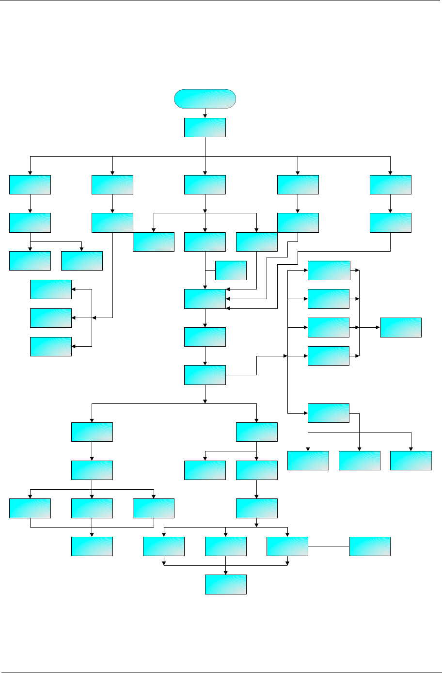
The flowchart on the succeeding page gives you a graphic representation on the entire disassembly sequence
and instructs you on the components that need to be removed during servicing. For example, if you want to
remove the system board, you must first remove the then disassemble the inside assembly frame in that order.
Start
Battery
HDD Cover
Mini PCI
Cover
ODD Module DIMM Cover
M3L4*1 M2.5L6*1
Keyboard
HDD Module
HDD Holder HDD Drive
ODD Bracket
M2L3*4
Optical Drive
Optical Device
Board
ODD
Connector
M2L4*2
Hinge Covers
Keyboard
Support Plate
Middle Cover
RTC Battery
Memory
(upgrade)
Wireless LAN
Card
Memory/
MDC
board
Disconnect
Bluetooth
LCD Module
M2.5L5*4
Upper
Assembly
M2.5L6*2
M2L6*12
Lower
Assembly
Toucpad
Cover
Lower case
left cover
Lower case
right cover
Touchpad
Button
Touchpad
Scroll Key
Touchpad
Touchpad
Cable
Main Board
Assembly
Heatsink
Module
Speaker
Module
Extension
Board
CPU
Main Board
Inverter
Button Board
LED Board
Main Antenna
LCD/w cable,
brakets
LCD Panel
LCD Brackets LCD
LCD Coaxial
Cable
M2L8*3
M2L4*4
M2L4*2
M2L4*1
M2L4*2 M2L4*1
*4
*1 *2
M2L4.5*2
M2L4.5*2
M2L4.5*2
M2L4.5*2
M2L3*8
for CMO