


78 Chapter 5
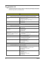
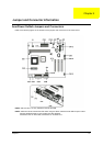
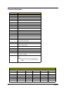
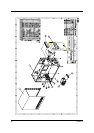
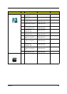
Connector Description
NOTE:
*: Default setting
NOTE:
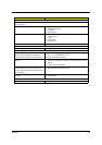
There’s only 66/100 MHz allowable speed limit for 66/133 MHz SDRAM.
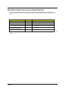
Connector No. Description
CN1 PS/2
CN2 USB/LAN
CN3 ATX power connector
CN4 COM port
CN5 Parallel/VGA/serial port 2
CN7 IDE2
CN8 IDE1
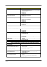
CN9 GAME/MIDI
CN11 Audio CD connector
CN12 Floppy Disk Drive
CN13 Hard Disk Drive LED
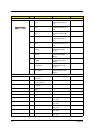
CN16 Fax voice modem
CN18 WAKE ON LAN
CN19 36-pin USB/AUDIO connector
CN20 RF connector
CN21 Slim CD-ROM connector
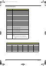
JP1 1/2: Disable on board codec
2/3: Enable on board codec
JP2 PWR LED
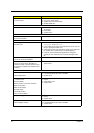
JP3 1/2, 4/5: 4M flash ROM
2/3, 5/6: 2M flash ROM
JP4 Reset
JP5 Intrusion
JP6 LAN LED
JP7 PWR switch
JP11 1/2: Clear CMOS
2/3: NOP, no operation
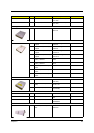
SW1 ON
OFF*
NOTE:
Set this to ON when CPU is packaged by
FCPGA, hence, it can avoid system resource
waste.
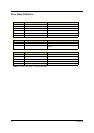
Socket 370 core/bus clock ratio
S1
SW4 SW3 SW2 SW1 CPU SDRAM
00 0066100
0 0 0 1 100 100
0 0 1 1 133 100
0 1 0 1 100 133
0 1 1 1 133 133
10 006666