


Chapter 4 65
POST Check Points
When POST executes a task, it uses a series of preset numbers called check point to be latched at port 80h,
indicating the stages it is currently running. This latch can be read and shown on a debug board.
Table D-1 describes the Acer common tasks carried out by POST. A unique check point number represents
each task.
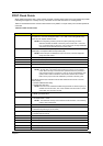
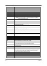
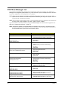
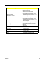
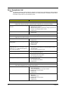
Table D-1 POST Check Points
Check Point Description
04H Determines if the current booting procedure is from cold boot (press reset button or turn
the system on), from warm boot (press CTRL + ALT + DEL or from exiting BIOS setup.
Check CPU ID, dispatch shutdown Path.
NOTE:
At the beginning of POST, port 64 bit 2 (8042 system flag) is read to
determine whether this POST is caused by cold or warm boot. If it is a cold
boot, a complete POST is performed. If it is a warm boot, the chip initialization
and memory test is eliminated from he POST routine.
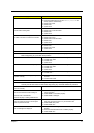
08H Disables Non-Maskable Interrupt (NMI), Alarm Interrupt Enable (AIE), Periodical Interrupt
Enable (PIE), and Update-ended Interrupt Enable (UIE).
NOTE:
These interrupts are disabled in order to avoid any mis-action happened
during the POST routine.
09H Initializes chipset point (I)
10H DMA Controller (8327) test and initialization.
14H System timer (8254) test and initialization
18H Memory refresh test; refresh occurrence verification (IRQ0)
1CH 1. Verifies CMOS shutdown byte, battery and check sum.
NOTE:
Several parts of the POST routine require the system to be in protected
mode. When returning to real mode from protected mode, the processor is
reset, therefore POST is re-entered. In order to prevent re-initialization of the
system, POST reads the shutdown code stored in location 0Fh in CMOS
RAM. Then it jumps around the initialization procedure to the entry point.
The CMOS shutdown byte verification assures that CMOS 0Fh area is fine to execute
POST properly.
2. Initializes CMOS default setting
3. Initializes RTC time base
NOTE:
The RTC has an embedded oscillator that generates 32.768 Hz frequency. To
initialize the RTC time base, turn on this oscillator and set a divisor to 32768
so that RTC can count time correctly.
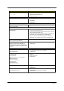
1EH 1. Search DRAM existence on each DRAM slot
2. DRAM type determination
2CH 1. Tests 384K base memory
2. Set default SS:SP = 0:400
NOTE:
The 384K base memory area is tested for POST execution. The remaining
memory ares is tested later.
30H System shadow RAM
20H 1. Tests keyboard controller (8041/8042)
2. Determines keyboard type (AT, XT, PS/2)
24H 1. Test programmable interrupt controller
2. Initializes system interrupt
26H Initializes GPIO
34H DRAM sizing
36H Initialize I/O APIC
3CH Sets interrupt service for POST
2DH Set CPU (s) multiple
3FH Enables/Disables USB Host Controller