


vii
System Tour 1
Features 1
System Components 3
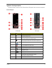
Front Panel 3
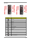
Rear Panel 4
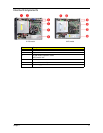
Internal Components 5
System LED Indicators 6
System Utilities 7
CMOS Setup Utility 7
Entering CMOS setup 8
Navigating Through the Setup Utility 8
Setup Utility Menus 9
System Disassembly 23
Pre-disassembly Procedure 24
Main Unit Disassembly 25
X1700 model 25
X270 model 26
Screw List 27
Removing the Side Panel 28
Removing the Front Bezel 29
Removing the Heat Sink Fan Assembly 30
Removing the Processor 32
Removing the Optical Drive 34
Removing the Hard Disk Drive 37
Removing the Power Supply 40
Removing the Memory Modules 42
Removing the VGA Card (X1700 model) 43
Removing the TV Tuner Card (X1700 model) 44
Removing the Front I/O and Card Reader Boards 45
Removing the Mainboard 49
Removing the Power Switch and LED Cables 51
Removing the LAN Activity and HDD LED Cables (X270 model) 54
System Troubleshooting 55
Hardware Diagnostic Procedure 55
System Check Procedures 56
Power System Check 56
System External Inspection 56
System Internal Inspection 56
Beep Codes 57
Online Support Information 58
System Block Diagram and Board Layout 59
System Block Diagram 59
Board Layout 60
Mainboard 60
System Jumpers 62
Table of Contents