Installation LTPH-UM-1088-02, Issue 2
8 January 3, 2002 ThinMux Chassis
WIRING THE COMMON ACCESS PANEL
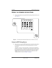
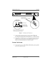
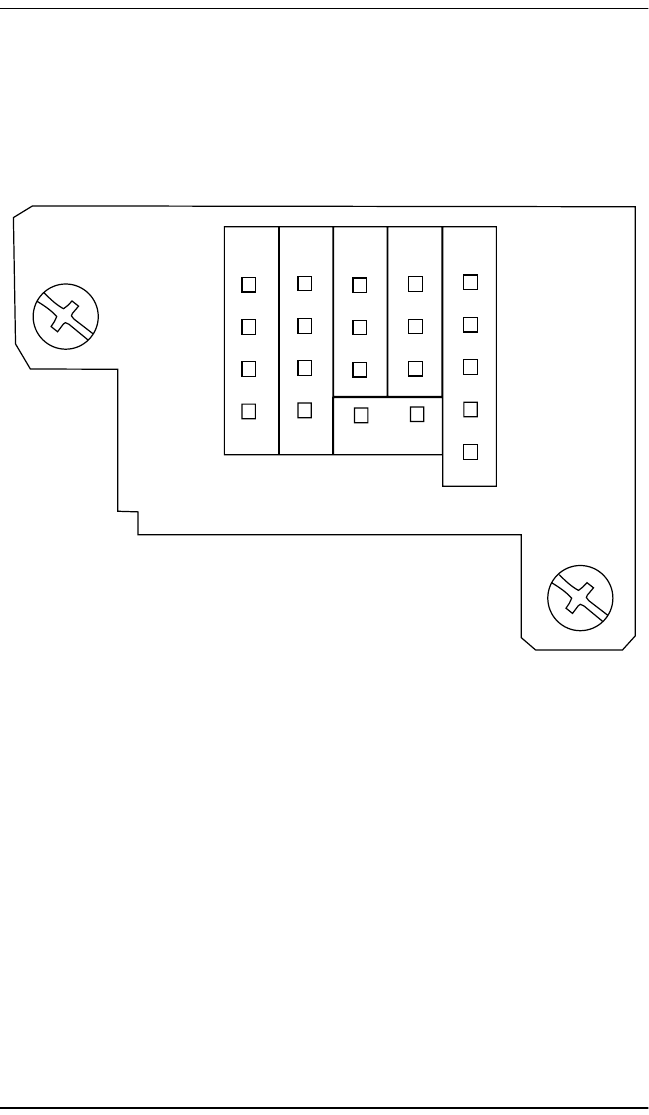
1 Unscrew the common access panelhold-down lugs and remove the cover
(see Figure 4).
Figure 4. Wire-Wrap Pin Positions/Common Access Panel (rear view)
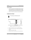
Connect a BITS Timing Source
2 Determine if you require a BITS timing source connection to the chassis;
if so, the chassis must first have a line termination prior to chassis
connection.
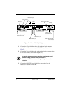
The BITS concept is used for interoffice synchronization distribution.
Each line source, Bits A and Bits B, must be terminated. ADC provides
this termination through external termination blocks (product catalog
TERM-100) placed on wire-wrap terminal posts on the rear of the
ThinMux chassis as shown in Figure 5 on page 9.
Test
Access
CRIT
VIS
CRIT
AUD
Bits Alarm
B-
B+
A-
A+
TTIP
TRING
RTIP
RRING
Frame
GND
Frame
GND
NO NO
COM COM
NU NU
FE
MIN
MAJ
CRIT
COM


