LTPH-UM-1088-02, Issue 2 List of Figures
ThinMux Chassis December 7, 2001 vii
LIST OF FIGURES
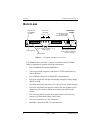
1. Backplane Interfaces (rear view) .......................................................... 2
2. ThinMux Chassis in a CO Rack............................................................ 6
3. Installing the Fan Module (FB1)........................................................... 7
4. Wire-Wrap Pin Positions/Common Access Panel (rear view).............. 8
5. Installing Line Terminators................................................................... 9
6. Battery Supply Connector (rear view) ................................................ 10
7. DS3 or STS-1 Shelf Configuration..................................................... 12
8. Male Cable Connector Into Female Backplane Connector................. 14
LIST OF TABLES
1. T1/E1 Receive Pin Assignments......................................................... 14
2. T1/E1 Transmit Pin Assignments ....................................................... 16
3. RS-232 Craft Interface Pin Assignments............................................ 17
4. Ethernet 10/100BASE-T Pin Assignments......................................... 17


