Installation LTPH-UM-1088-02, Issue 2
12 January 3, 2002 ThinMux Chassis
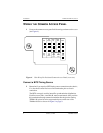
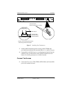
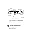
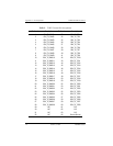
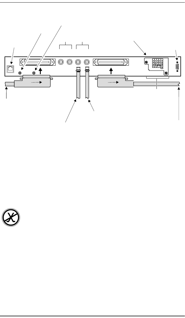
Figure 7. DS3 or STS-1 Shelf Configuration
1 Connect the 32-pair shielded cable, with amphenol male connector
coming from the cross-connect, to the DSX-1 input (Rx) as shown in
Figure 7.
2 Connect the 32-pair shielded cable, with amphenol male connector going
to the cross-connect, to the DSX-1 output (Tx).
3 Connect the DS3/STS-1 coaxial cable for data coming from the
DS3/STS-1 network to Line 1 Rx.
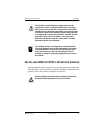
The metallic telecommunication interface should not be routed
from the building premises unless connected to
telecommunication devices providing primary and secondary
protection.
ESD strap input
DS3 or STS-1 (Out)
DS3 or STS-1 (In)
Common access panel
Craft port
Ethernet
10/100BASE-T
Line 1
Tx
Line 2
DSX-1 output (transmit)
to cross-connect
Rx Tx Rx
DSX-1 input (receive)
from cross-connect
Chassis ground
Alarms, p
and frame ground
ower,
Test
Access
CRIT
VIS
CRIT
AUD
Bits Alarm
B-
B+
A-
A+
TTIP
TRING
RTIP
RRING
Frame
GND
Frame
GND
NO NO
COM COM
NC NC
FE
MIN
MAJ
CRIT
COM
RTN B]
-48 B
RTN A
-48 A
FGND
Craft
RS-232


