


LTPS-UM-8013-03 Installing the BNC Panel
D3LX CO and RMT Modules August 30, 2002 7
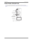
INSTALLING THE BNC PANEL
OVERVIEW
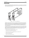
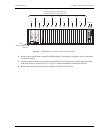
The ADC BNC Panel consists of 14 pairs of 75Ω BNC connectors that are part of a system that converts an
electrical DS3 circuit at the CO site into an optical signal that uses WDM to transmit a signal across one
single-mode fiber to a CPE site. The BNC Panel can support 7 working D3LX lines and 7 protection D3LX lines.
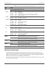
(Table 2 on page 8 lists each working slot location as labelled on the front panel of the chassis and its
corresponding protection slot.)
The D3LX CO (CO module) converts the optical signal at the CO site and the D3LX RMT (remote module)
converts the optical signal back into an electrical DS3 and transmits the signal back to the D3LX CO residing in
the Loop Extender Chassis (LEC).
A BNC Panel and ADC adapter cables are required when D3LX modules are installed. Prior to ordering ADC
adapter cables, measure the distance between the BNC Panel and the chassis. For more information about
installing D3LX modules, refer to “Installing a D3LX CO Module in an LEC” on page 9.
INSTALLATION OF THE PANEL
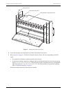
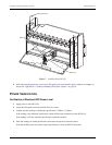
1 Mount the panel in the rack.
2 Secure the panel to the rack by using the provided screws.
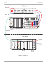
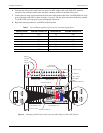
3 On the front of the panel, connect the DS3 IN (transmit) and DS3 OUT (receive) coax cables as shown in
Figure 4 on page 8. Note the connector numbers on the BNC panel.
In every group of 4 slots, such as 1-1 through 1-4, the right most two slots have cables plugged into the bottom
2 wire-wrap pins (T1 and R1), and the two left most slots have cables plugged into the top 2 wire-wrap pins
(T and R). If it is a protected system or a single D3LX module, then slots 1-2 and 1-4 do not have cables.
For example, a D3LX CO module plugged into slot 1-1 of the chassis or in a 2 D3LX protected system:
• The DS3 receive cable plugs into the bottom 2 pins T1 and R1 of slot 1-1. This is the DS3 that the D3LX
receives.
• The DS3 transmit cable is plugged into the top 2 pins T and R of slot 1-3. This is the DS3 that the D3LX
transmits.
In another example, for a D3LX CO module plugged into slot 1-3 of the chassis in an unprotected system:
• The DS3 receive cable plugs into the bottom 2 pins T1 and R1 of slot 1-2. This is the DS3 that the D3LX
receives.
• The DS3 transmit cable plugs into the top 2 pins T and R of slot 1-4. This is the DS3 that the D3LX
transmits.
4 From the rear of the panel, connect the coax end of an ADC adapter cable to the DS3 IN (receive) connector.
The connector number must match the connector number on the front of the panel.
5 Connect the wire-wrap conversion block end of the same ADC adapter cable to the T and R EQUIP wire-wrap
posts on the back of the LEC as shown in Figure 4 on page 8. The top of the conversion block mates with the
T and R LINE wire-wrap posts to prevent improper connection.
Prior to installing the ADC adapter cables (BNC-3-CBL-WW), remove any existing wires from the
LINE wire-wrap row on the back of the LEC.