


LTPS-UM-8013-03 Remote Configuration
D3LX CO and RMT Modules August 30, 2002 35
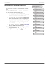
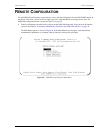
1 From the Main menu, select 3. Unit Configuration.
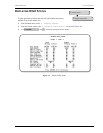
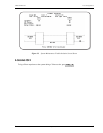
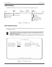
2 Within the Unit Configuration screen (see Figure 22 on page 34), select the Group number that corresponds to
the D3LX circuit you want to configure, based on the module’s position in the remote unit.
3 Select each field parameter and move from field to field as shown in Table 7. Assign the selections by
pressing .
4 Repeat Steps 1 and 2 for each D3LX RMT system installed in the chassis.
Leave Unit Service State field set to OOS (Out of Service) until the Unit Equip State has been set.
This prevents false alarms. Set the Unit Service State to IS (In Service).
Table 7. Unit Configuration Fields–D3RCAM Version 1.0 or later
Field Name Type Options Description Default
Unit Equip State Toggle EQUIPPED Establishes communication with D3RCAM.
Module must be set to EQUIPPED before
remaining selections are allowed.
UNEQUIPPED
UNEQUIPPED No communication with D3RCAM.
Unit Service State Toggle IN SERVICE Places the unit in service and allows equipment
alarm reporting by the D3RCAM. Must be set to
IS for reporting of equipment alarms.
OOS
OUT OF SERVICE Removes unit from service and stops
equipment alarm reporting by the D3RCAM.
Unit Protect State Toggle PROTECTED Line protection Unprotected
UNPROTECTED No protection
DS3 Provisioned Toggle YES Brings up DS3 default settings and allows
configuration changes.
NO
NO No configuration changes allowed.
DS3 Service State Toggle IN SERVICE Select IS after completing the remaining con-
figurations.
OOS
OUT OF SERVICE Leave this field at OUT OF SERVICE (versus IN
SERVICE) at this time to avoid undesirable
reporting of alarms.
Optical Service State Toggle IN SERVICE Places facility in service and enables T3 alarm
reporting by the D3LX RMT.
OOS
OUT OF SERVICE Removes facility from service and stops T3
alarm reporting by the D3LX RMT.
Optical BER Alarm
Threshold
Toggle Set to OFF or set
between 10
-6
and 10
-10
The average Bit Error Ratios of both the
incoming optical signals are monitored by the
D3LX RMT. By monitoring BERs, the D3LX CO
is capable of triggering a minor alarm when any
of the monitored signals degrades below the
BER threshold level.
10
-8
Optical BER Switch
Threshold
Toggle Range from 10
-4
to
10
-10
Sets the threshold at which the APS will be
executed.
10
-6
DS3 Remote LBO Toggle 0–225 ft., 226–450 ft. The DS3 signal output provides standard DSX
signal levels which can be compensated for at
various distances, such as cable length.
0–225 ft.
DS3 Local LBO Toggle 0–225 ft., 226–450 ft. The DS3 signal output provides standard DSX
signal levels which can be compensated for at
various distances, such as cable length.
0–225 ft.
ENTER