


Z8F04A08100KIT Development Kit
User Manual
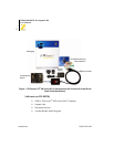
Development Board UM018702-0505
10
Jumpers and Settings
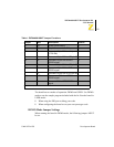
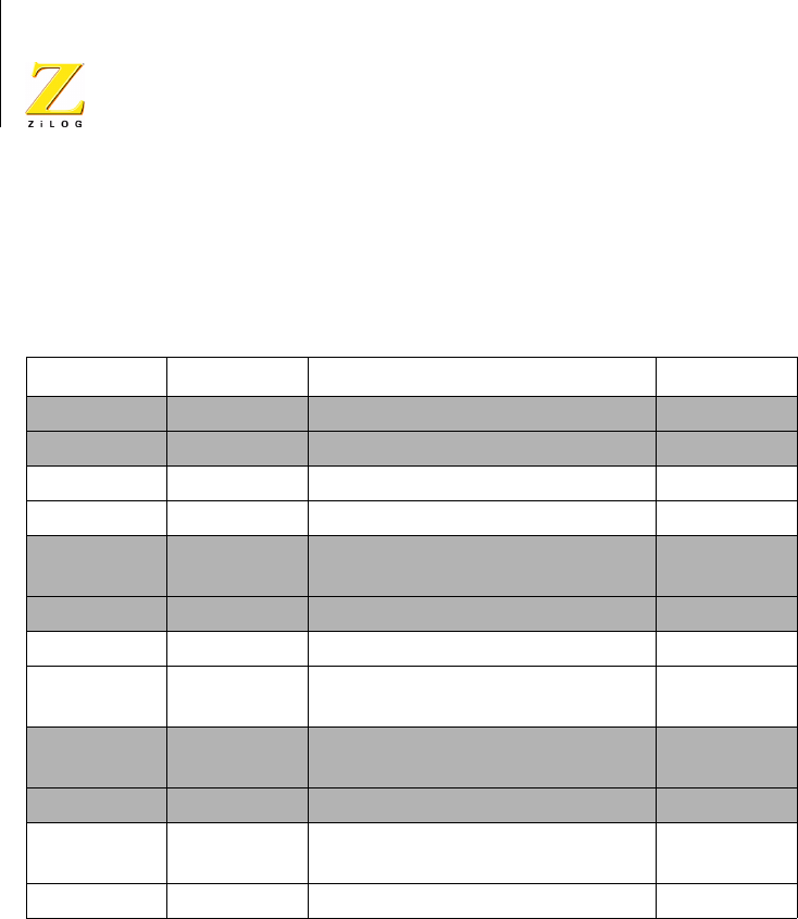
Table 1 provides information on jumper functions.
Table 1. Z8F04A08100KIT Jumper Functions
Jumper State Description Default
J1* OUT Enables RS-232 interface X
IN Disables RS-232 interface
J2* OUT Enables IrDA interface X
IN Disables IrDA interface
J3 1-2 Connects U5 pin PA0 to Green
LED D2
X
2-3 Connects U5 pin PA0 to JP2 pin 18
J4 OUT Disconnects PA0 from debug pin X
IN Connects PA0 to DBG pin 4 on ZDI
port P3.
J5 1-2 Connects U5 pin PA1 to yellow
LED D3
X
2-3 Connects U5 pin PA1 to JP2 pin 20
J6 1-2 Connects U5 pin PA2 to red LED
D4.
X
2-3 Connects U5 pin PA2 to JP2 pin 22