


Z8F04A08100KIT Development Kit
User Manual
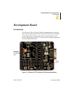
UM018702-0505 Development Board
11
The board has two modes of operation: DEMO and USER. Use DEMO
mode to run the sample program included with the kit. Run the board in
USER mode:
•
When using the ZDI port to debug your code.
•
When configuring the board to run your own prototype code.
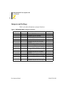
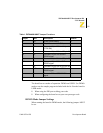
DEMO Mode Jumper Settings
When running the board in DEMO mode, the following jumpers MUST
be set:
J7 OUT DEMO mode setting X
IN Chip U5 resets when SW1 pressed
J8 1-2 Connects U5 pin PA3 to J11 pin 1
(CTS0 EN)
X
2-3 Connects U5 pin PA3 to JP2 pin 35
J9 1-2 Connects U5 pin PA4 to RXD
RS232 signal
X
2-3 Connects U5 pin PA4 to JP2 pin 35
J10 1-2 Connects U5 pin PA5 to TXD
RS232 signal
X
2-3 Connects U5 pin PA5 to JP2 pin 36
J11 OUT Disconnects PA3 from CTS0
RS232 signal
X
IN Connects PA3 to CTS0 RS232
signal
Note: * These jumpers must not be OUT at the same time
Table 1. Z8F04A08100KIT Jumper Functions
Jumper State Description Default