


Total Access 1248 Expansion DSLAM Installation and Maintenance Practice
2-2 61179641L5-5C
EXPANSION
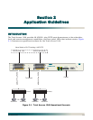
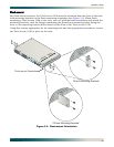
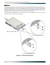
Up to four Total Access 1248 systems can be connected together (see Figure 2-2). One of the
units must be a Total Access 1248 Host unit (e.g., P/N 1179641L4) and the others are Total
Access 1248 Client units (P/N 1179641L5).
The client units (also referred to as Expansion units) have RJ-45 jacks, labeled
EXPANSION IN
and
EXPANSION OUT, for the purpose of expanding one to another.
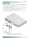
The Total Access 1248 host unit provides the network connection for all of the client units. All
provisioning for the clients is completed through the host unit.
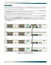
Beginning with the host, a Category 5e, non-crossover cable is connected from the
EXPANSION
OUT
jack of the host to the EXPANSION IN jack of the first client unit. Further connections
between client unit
EXPANSION OUT jacks to EXPANSION IN jacks continue until a total of up to
three client units have been connected with the third client unit having only a connection to
the
EXPANSION IN jack.
Figure 2-2. Expansion Cabling
Client 1
Client 2
Client 3
OUT
Host
FAN MODU LE
1179675L1
ALARM
CRAFT
PWR
ALM
1179641L4
TOP:POTS BOTTOM: ADSL+POTS PORTS 1-24
TOP:POTS BOTTOM: ADSL+POTS PORTS 25-48
ETHERNET
EXPANSION
T1/E1 1-8
-48V
.....
,5.0A
USE COPPER CONDUCTORS ONLY!
T1/E1
A B
-48V RET -48V RET
5
6
7
8
A
FAN MODULE
1179675L1
CRAFT
PWR
ALM
1179641L5
TOP:POTS BOTTOM: ADSL+POTS PORTS 1-24
TOP:POTS BOTTOM: ADSL+POTS PORTS 25-48
OUT
EXPANSION
-48V
.....
,5.0A
USE COPPER CONDUCTORS ONLY!
A B
-48V RET -48V RET
EXPANSION
IN
FAN MODULE
1179675L1
CRAFT
PWR
ALM
1179641L5
TOP:POTS BOTTOM: ADSL+POTS PORTS 1-24
TOP:POTS BOTTOM: ADSL+POTS PORTS 25-48
OUT
EXPANSION
-48V
.....
,5.0A
USE COPPER CONDUCTORS ONLY!
A B
-48V RET -48V RET
EXPANSION
IN
FAN MODULE
1179675L1
CRAFT
PWR
ALM
1179641L5
TOP:POTS BOTTOM: ADSL+POTS PORTS 1-24
TOP:POTS BOTTOM: ADSL+POTS PORTS 25-48
OUT
EXPANSION
-48V
.....
,5.0A
USE COPPER CONDUCTORS ONLY!
A B
-48V RET -48V RET
EXPANSION
IN