


Installation Steps
61179641L5-5C 3-9
Fans/Fan Filter
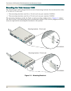
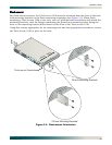
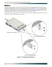
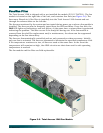
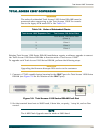
The Total Access 1248 is shipped with a pre-installed fan module (P/N 1179675L1). The fan
module is located on the right side of the unit, and contains four fans (see Figure 3-6). The
fans move filtered air (if the filter is installed) into the Total Access 1248 chassis and out
through the exhaust slots on the left side.
The fans are monitored by the system and are tested during power-up or when a fan module is
installed. The fans can also be manually tested from the Self-test Menu. If any fan fails, the
PWR LED lights red indicating a self-test failure. At the same time, a minor alarm is generated
indicating the problem. This also occurs if the fan(s) fail during use. If the fan module is
removed from the shelf for replacement and/or maintenance, the alarm can be suppressed
depending on the fan alarm delay.
The fans are thermostatically controlled and are only powered on when necessary. Initially,
only one fan is activated. The fans are alternated to maintain the specified temperature level.
If the temperature continues to rise, all fans are used at the same time. In the event the
temperature still remains too high, the ADSL circuits are shut down until a safe operating
temperature is reached.
The fan module and fan filter are field-replaceable.
Figure 3-6. Total Access 1248 Fan Module
FAN MODULE
1179675L1
FAN MODULE
1179675L1