


61180403L1-5B Issue 2, December 2004 3
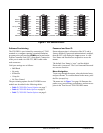
Instructions for Installing the Module
To install the FXS/DPO, perform the following steps:
1. If present, remove the Access Module Blank (P/N
1175099L1) from the appropriate access module
slot of the Total Access chassis.
2. Pull the ejector latch, located on the lower left-
hand side of the FXS/DPO front panel, from its
closed position.
3. Hold the FXS/DPO by the front panel while
supporting the bottom edge of the module with the
ejector latch opened to engage the chassis edge.
4. Align the module edges to fit in the lower and
upper guide grooves for the access module slot.
5. Slide the module into the access module slot.
Simultaneous thumb pressure at the top (above the
STATUS LED) and at the bottom (below the
electrostatic caution symbol) of the module will
ensure that the module is firmly positioned against
the backplane of the chassis.
6. Secure the FXS/DPO in place by pushing in on the
ejector latch.
When the FXS/DPO first powers up it performs the
power up self-tests. Once the power up self-test is
complete, the status LEDs will reflect the true state of
the hardware.
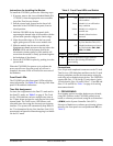
Front Panel LEDs
The FXS/DPO provides front panel LEDs to display
status information. See Table 2 for a listing of the front
panel LEDs and their indications.
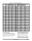
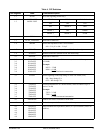
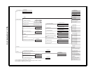
Time Slot Assignment
For time slot assignments in the Dual T1 mode and in
the Quad T1 mode, see Table 3 on page 4. The Total
Access 1500 platform can have multiple time slots in
the T1 data stream assigned to each physical slot in the
channel bank. The Total Access 1500 allows craft-
selectable time slots using the electronic provisioning
interface. The system will automatically map DS0s in
the T1 as determined by the Line Interface Unit (LIU)
operational configuration. Manual mapping is available
via the LIU menu.
Connections
Four 50-pin male amphenol connectors on the 23-inch
Total Access 1500 backplane and three on the 19-inch
chassis packplane provide the interconnect wiring for
each of the access module physical slots. The FXS/DPO
requires
P1 (Pair 1 T/R) on the 23-inch chassis. In the
19-inch chassis, Slots 1-6 use
P1, Slots 7-12 use P2, and
Slots 13-18 use
P3. See Table 3 on page 4 for wiring
interconnect details.
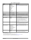
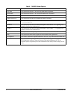
3. PROVISIONING
Provisioning options are either hardware provisioned;
using DIP switches on the FXS/DPO printed circuit
board, or software provisioned; using the craft interface
(
ADMIN) on the System Controller Unit (SCU).
Selection of hardware or software provisioning is deter-
mined by the front panel recessed pushbutton
AP (see
Table 2).
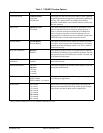
Table 2. Front Panel LEDs and Switch
Label Condition Description
BUSY
Off
Green
Yellow
Red
Module is in an on-hook or
idle condition
Module is in an off-hook or
busy condition
Module is in a digital or
metallic test
Module failure has been
detected
REM
Green
Off
Module software provisioned
by Line Interface Unit (LIU)
Module hardware provisioned
by Dip Switches
SW1, SW2,
SW3, and SW4
Switch Description
AP
Recessed pushbutton toggles between
hardware provisioning and software
provisioning