


4 Issue 2, December 2004 61180403L1-5B
Hardware Provisioning
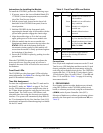
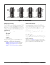
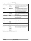
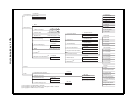
DIP switches
SW1, SW2, SW3, and SW4 are used to
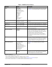
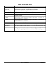
provision many of the FXS/DPO options. Table 4 on
page 5 summarizes the options provisioned by the DIP
switches. Figure 2 on page 6 provides a graphic detail
of the four switches and the printed circuit board
markings.
NOTE
Manual switches can only be used for the
negative portion of the TLP range. For
example, a switch setting of TX32 corresponds
to –3.2 dB.
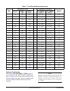
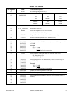
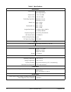
Table 3. Time Slot and Wiring Interconnect
Physical
Slot
Associated T1/DS0
Port
Amphenol Connections
Interconnect
Wiring
Dual T1
Quad T1
(D4)
Quad T1
(D1D)
23” Chassis
1180001L1
19” Chassis
1180019L1
1 A1 A1 A1 1 P1 - 26/1 P1 - 26/1 T/R
2 A3 A5 A9 1 P1 - 27/2 P1 - 30/5 T/R
3 A5 A9 A17 1 P1 - 28/3 P1 - 34/9 T/R
4 A7 A13 A2 1 P1 - 29/4 P1 - 38/13 T/R
5 A9 A17 A10 1 P1 - 30/5 P1 - 42/17 T/R
6 A11 A21 A18 1 P1 - 31/6 P1 - 46/21 T/R
7 A13 B1 B1 1 P1 - 32/7 P2 - 26/1 T/R
8 A15 B5 B9 1 P1 - 33/8 P2 - 30/5 T/R
9 A17 B9 B17 1 P1 - 34/9 P2 - 34/9 T/R
10 A19 B13 B2 1 P1 - 35/10 P2 - 38/13 T/R
11 A21 B17 B10 1 P1 - 36/11 P2 - 42/17 T/R
12 A23 B21 B18 1 P1 - 37/12 P2 - 46/21 T/R
13 B1 C1 C1 1 P1 - 38/13 P3 - 26/1 T/R
14 B3 C5 C9 1 P1 - 39/14 P3 - 30/5 T/R
15 B5 C9 C17 1 P1 - 40/15 P3 - 34/9 T/R
16 B7 C13 C2 1 P1 - 41/16 P3 - 38/13 T/R
17 B9 C17 C10 1 P1 - 42/17 P3 - 42/17 T/R
18 B11 C21 C18 1 P1 - 43/18 P3 - 46/21 T/R
19 B13 D1 D1 1 P1 - 44/19 N/A T/R
20 B15 D5 D9 1 P1 - 45/20 N/A T/R
21 B17 D9 D17 1 P1 - 46/21 N/A T/R
22 B19 D13 D2 1 P1 - 47/22 N/A T/R
23 B21 D17 D10 1 P1 - 48/23 N/A T/R
24 B23 D21 D18 1 P1 - 49/24 N/A T/R