


2 PRELIMINARY Issue 1, June 2004 64150WALO3L7-5A
The cabinet equipment access door has a full-view
safety-glass window. The swing out equipment housing
section has vent louvers on the top. The wallmount
support frame has cable access openings on the bottom.
A ground bus bar is mounted to the bottom inside of the
cabinet. Vertical equipment racks are sized for 19-inch
chassis components.
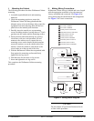
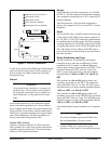
See Figure 2 for a rear view of cabinet arrangement.
Figure 2. Wallmount Cabinet Rear View
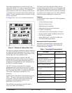
The cabinet is configured with the two PS/BCs mounted
to a panel installed bottommost in the cabinet. Viewed
from the front, the left side PS/BC is the primary A-unit
and the right side is the redundant B-unit.
Mounted above the power supplies is the fiber
management shelf. It has a swing out door that gives
access to the 6-position fiber termination panel. It is
designed to accommodate fiber cable management for
two OPTI-3 controller modules.
The OPTI-3 chassis is mounted above the fiber
management shelf. It has slots for two OPTI-3 circuit
boards: the in-service unit and an optional redundant
unit if installed. Each OPTI-3 can feed three DS3 NIU3
circuit cards. The design is intended for 1-to-1
protection.
The DS3 NIU3 3-Slot chassis is mounted next above the
OPTI-3. The NIU3 chassis has slots for three NIU3
circuit cards. Three test cards are provided for this
installation: the DS3 Monitor and Test Card
(DS3 MTC), P/N 1212071L1.
The MX2800 is mounted above the NIU shelf. It
converts one DS3 into 28 DSX-1s.
The Trimm 10x10 fuse and alarm (F&A) panel is
mounted topmost in the cabinet. It receives primary and
secondary (redundant) power from the two PS/BCs. The
F&A panel has terminals and fuse protection capability
for primary and secondary power for a fully populated
cabinet plus spare capability for customer use.
Features
The Wallmount Cabinet supports the following features
and functions:
• 19-inch rackmount design
• Key lock security access
• Redundant power capability
• Independent frame ground connections
• Compact configuration
• Convenient access to front and back of chassis
• Factory wired for quick installation and turn-up
• FCC and UL compliant
• Meets NEBS Level 3 (all GR-63-CORE and
GR-1089-CORE requirements)
Associated Unit Documentation
Individual unit documentation with detailed infor-
mation exists for each element of the Wallmount
Cabinet solution (see Table 1).
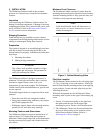
1 RMU Fiber Management Shelf
Table 1. Associated Documentation
Document ADTRAN P/N
OPTI-3 Rackmount Chassis
Job Aid
61184003L1-22
Total Access OPTI-3
Controller Module Installation
and Maintenance Practice
61184002L1-5
AC/DC Power Supply and
Battery Charger Job Aid
61175043L3-22
DS3 NIU3 3-Slot Shelf Unit
Job Aid
61212073L1-22
DS3 Monitor and Test Card
Job Aid
61212071L1-22
MX2800 Chassis Job Aid
61200290L1-22
Fiber splice tray Vendor provided
F&A panel guide Vendor provided