


4 PRELIMINARY Issue 1, June 2004 64150WALO3L7-5A
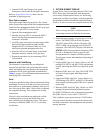
I. Mounting the Cabinet
The following procedure describes Wallmount Cabinet
mounting:
1. Assemble required hand tools and mounting
hardware.
2. Check the mounting position to ensure the
Wallmount Cabinet will hang plumb and that
adequate space exists on the hinge side to open the
equipment rack main housing, then drill the two
pilot holes at the marked point locations.
3. Partially insert the outside two top mounting
screws including washers, leaving about a 1/2-inch
gap between the washer and the mounting surface.
4. Ensure the door and main housing are securely
closed then, with two craft personnel, lift and
maneuver the cabinet so as to capture the two
mounting screws on the bracket keyhole notches,
ensure the washers are on the cabinet side of the
notches. Allow the cabinet to slide down so the
screw heads are at the top end of the slots.
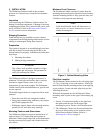
5. With the Wallmount Cabinet thus suspended, hold
firm against the mounting surface and firmly
tighten the two lag screws.
6. Drill the holes for the other six lag screws.
7. Insert and tighten the six lag screws
This completes the Wallmount Cabinet mounting
procedure.
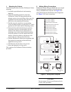
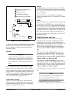
II. Making Wiring Connections
Wallmount Cabinet wiring is labeled and cut to length
with the appropriate terminals or keyed connectors
factory assembled and connected. See Figure 4 for
wiring block diagram identification and arrangement.
See Figure 5 for circuit connections.
Figure 4. Wiring Block Diagram
CAUTION
Do not connect AC power until instructed to do
so later in this procedure.
MX2800
PRI SEC
OPTI-3
NIU3
Alarms
PS/BC A
F&A
H
I
I
J
AC Power to PS/BC A
AC Power to PS/BC B
Primary Power to F&A Panel
Redundant Power to F&A Panel
Primary Power to OPTI-3
Primary Power to NIU3
Primary Power to MX2800
Secondary Power to OPTI-3
Secondary Power to NIU3
Secondary Power to MX2800
A
B
C
D
E
F
G
H
J
A
B
C
D
E
F
G
PS/BC B
Alarms
Alarms