


64150WALO3L7-5A Issue 1, June 2004 PRELIMINARY 5
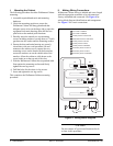
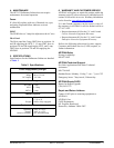
Figure 5. Circuit Connections
A cable access plate on the Wallmount Cabinet bottom
panel provides the entry point for office ground, AC
power, network coax/fiber connections, and other
associated wiring.
Ground
WARNING
All grounds must terminate at an approved
ground source. Check metal to metal contact
on all ground connections. Do not combine or
stack connections. Verify ground circuit conti-
nuity.
At the inside bottom left of the wallmount support
frame is the cabinet ground bus bar. It has multiple
screw compression terminals for ground connections.
The ground bus is the primary cabinet ground source.
The bus bar is ground connected to the support frame
with a bolt arrangement. All shelf components are
factory connected to the ground bus bar.
Cabinet Office Ground
Connect a customer-supplied, 10 AWG minimum,
office ground wire to one of the unused compression
terminals on the ground bus bar. This is the primary
cabinet to office ground connection.
Alarms
The PS/BCs have an alarm output jack (AC ALARM
OUTPUT). The alarm outputs are joined and are factory
wire-wrapped on terminal posts AUX-1 on the OPTI-3
chassis backplane.
The F&A panel has a fuse fail alarm output that is
factory wire wrapped to AUX-2 on the OPTI-3 chassis
backplane.
Power
The two PS/BC units (A and B) mount to the back side
of the battery. Each PS/BC power output originates at
the –54 VDC, 2A OUTPUT connection, and terminates
at a modular plug at the F&A panel. The F&A panel has
a mating connector for each PS/BC output plug. PS/BC
A supplies F&A panel A-side, PS/BC B supplies the B-
side. F&A panel circuitry allows the PS/BC units to
power share with one unit picking up the entire load if
the other unit fails.
Power Distribution and Fuses
The F&A panel has 10 individually fused output
terminals on the A-side and an additional 10 on the
redundant B-side. Terminal sets
1A and 1B supply
primary and secondary power input to the OPTI-3. The
associated front panel GMT fuses are 3 amp. The
OPTI-3 power input and return is on power sharing
terminals labeled
–48V A and RET, and –48V B and
RET.
F&A terminal sets
2A and 2B supply primary and
secondary power input to the NIU3. The associated
front panel GMT fuses are 1.5 amp. The NIU3 power
input and return is on power sharing terminals labeled
–48V A and RET, and –48V B and RET.
F&A terminal sets
3A and 3B supply primary and
secondary power input to the MX2800. The associated
front panel GMT fuses are 3 amp. The MX2800 power
input and return is on power sharing terminals labeled
–48V A and RET, and –48V B and RET.
The remaining F&A output terminals are for customer
use.
NOTE
For a fully redundant system each PS/BC must
have an independent AC power source.
1. Connect PS/BC unit A power wire quick
disconnect to F&A panel A-side quick disconnect.
MX2800
OPTI-3
NIU3
3 DS3s
1 DS3
Field
Network
C
D
B
E
Network OC-3 Feed to OPTI-3
DS3 Signal to NIU3
DS3 Signal to Field
DS3 Signal IN to MX2800
DS3 Signal OUT from MX2800
A
B
C
D
E
A