


6 PRELIMINARY Issue 1, June 2004 64150WALO3L7-5A
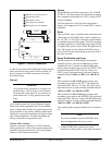
2. Connect PS/BC unit B power wire quick
disconnect to F&A panel B-side quick disconnect.
Refer to System Power Turn-Up below for the
remainder of applying power.
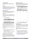
Fiber Optic Jumpers
Fiber optic jumper cables are provided. The 3-meter
cables connect the output of the fiber termination panel
inside the fiber management shelf to the SC style optic
connectors on the OPTI-3 circuit boards.
1. Open the fiber management shelf.
2. Partially insert an OPTI-3 card into the OPTI-3
chassis leaving the board mounted optical
connectors accessible.
3. Carefully route and connect an optic jumper cable
between the fiber termination panel and the
designated OPTI-3 connector. Make use of all
cable protection and management devices.
4. Insert the OPTI-3 card until firmly seated in the
backplane and lock with the lock/eject latch.
5. Repeat the procedure for the remaining OPTI-3
circuit boards.
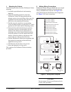
Network and Field Wiring
The customer is responsible for providing both
network-side and field-side optical fiber and coaxial
cables and making the connections to the appropriate
termination. Refer to the applicable documentation
(Table 1 on page 2) for information and instructions for
identifying these connections.
Final
All factory installed wiring is dressed and laced during
installation. For those wires that were craft connected,
dress and lace to workmanship standards, take special
care with optical fiber cables. Allow slack for opening
the equipment housing. This completes the wiring
connections.
After all wiring connections are made and verified,
reinstall protective covers and shields that were
removed during the installation process. This step is
necessary to maintain NEBS, UL, FCC, and safety
certification.
3. SYSTEM POWER TURN-UP
System Power Turn-Up assumes that the OPTI-3 and
NIU3 chassis have been outfitted with appropriate
circuit cards, default options factory set, and wiring
connections verified in accordance with the applicable
documentation and this Installation and Maintenance
Practice. If such is not the case complete that task first.
NOTE
Power turn-up should be conducted prior to
connecting network and field data connections.
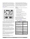
1. Insert both power supply AC plugs into a 120 VAC
source. The PS/BC LEDs will turn ON green.
The NIU3 status LEDs will turn ON green. The
OPTI-3 LEDs will go through various ON/OFF
sequences. The final OPTI-3 display will show the
STATUS LEDs ON green and the remaining LEDs
ON red or flashing red. Refer to specific unit
documentation for complete LED descriptions.
Test the power share and redundant functioning of
the PS/BCs:
2. Unplug PS/BC unit A AC source. Observe its LED
turning OFF. OPTI-3 and NIU3 LEDs should show
normal, indicating that PS/BC unit B picked up the
load.
3. Reinsert PS/BC unit A AC plug. The PS/BC LED
will turn ON green again indicating normal
operation.
4. Unplug the PS/BC unit B AC source. Observe its
LED turning OFF. OPTI-3 and NIU3 LEDs should
show normal, indicating that PS/BC unit A picked
up the load.
5. Reinsert PS/BC unit B AC plug. Observe its LED
turning ON green indicating normal operation.
For PS/BC LED details, refer to descriptions printed on
the PS/BC chassis, or Job Aid 61175043L3-22.
This completes system power turn-up. If LED indica-
tions are normal, operators can proceed with network
and field connections, and management and operation
turn-up functions.