


61225101L1-5B 17
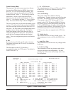
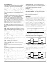
The NTU provides framing on the E1 port as
described in G.704 (sections 2.3 and 5) and G.706
(section 4) and G.736. In this mode, the data arriving
at the SHDSL interface need not contain any G.704
framing and the NTU generates the framing. One or
more services can be routed into time slots 1-31.
CRC-4 multiframe may be enabled or disabled. The
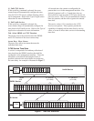
default is disabled. The NTU routes one or more
services from the SHDSL payload into time slots
1-31, as well as routing time slot 0. In this mode
G.704 framing is present in the data arriving on the
SHDSL interface, and this is passed transparently to
the G.703 interface.
NOTE
Not all time slots are necessarily routed between
the SHDSL and G.703 interface – some may be
routed from the SHDSL to the Nx64k interface.
See the CRC-4 Multiframe subsection.
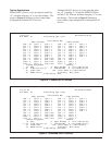
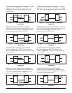
The NTU monitors the G.704 framing to detect errors
(and thus drive the NTU LEDs) and to determine the
value of the TS0 spare bits. The NTU transfers all
SHDSL payload time slots transparently through the
G.703 port without framing or monitoring. In this
mode the port operates as a 2 Mbit/s G.703 interface
without any G.704 framing. This implies that the
whole SHDSL payload comprises a single service.
The following alarm conditions can be monitored on
the G.703/G.704 interface (if applicable to the current
configuration):
1. AIS (Alarm Indication Signal)
2. BER (Excessive Bit Error Rate)
3. LOMFA (Loss of Multi-Frame Alignment)
4. LOF (Loss of Frame)
5. LOS (Loss of Signal)
6. RAI (Remote Alarm Indication)
7. Slip
When the NTU is configured for an unframed service
the only alarm available is LOS. Consequential
actions can only be undertaken if G.704 framing is
either delivered by the remote unit or is being
generated on the NTU. If framing is being generated
by the LT then the LT is responsible for these actions.
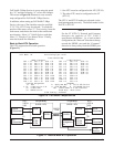
While any of the alarm states LOS, AIS, LOF,
LOMFA and BER are detected, the following
consequential actions will occur:
1. The remote alarm indication (bit 3 of the TS0
B- word) will be set as described in the G.704,
G.726 and G.706;
2. The G.703/G.704 alarm LED will be on,
3. AIS will be transmitted toward the network in all
corresponding data time slots.
NOTE
RAI assertion by the NTU can be disabled (the
default state) under the G.703 Options Screen by
the Customer RAI generation option.
When remote alarm indication is detected, the alarm
condition will be displayed on the front panel.