


4 61220010L2-5, Issue 3 61220010L2-5C
Wiring
The ADTRAN IDSL OCU-R may be mounted in any
standard T400/T200 housing, or the following
ADTRAN T400/T200 housings:
CAUTION
On span-powered units, ensure ground continuity
exists between the unit, the housing, and a known
approved ground source.
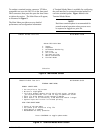
Span Power Applications
• Single Mount Housing P/N 1212007L1
• Dual Mount Housing P/N 1212008L1
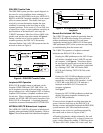
For 2-wire DDS deployment from D4/SLC-96 and
SLC-5 channel banks, a repeater powering U-BR1TE
is used to provide the metallic 2-wire DDS interface.
In these cases, the IDSL OCU-R is span-powered with
-120 Vdc and the customer premises installation
should include a span-powered mounting.
Local Power Applications
• Single Mount Housing P/N 1212007L2
For 2-wire DDS deployment from non-ADTRAN
digital loop carrier U-BR1TEs, the IDSL OCU-R must
be locally powered with customer provided AC. For
these applications a local powered T400/T200
mounting is required.
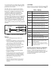
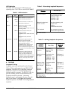
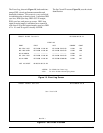
Table 3 shows the Compliance Codes for the IDSL
OCU-R. The IDSL OCU-R complies with the
requirements covered under UL 1459 third edition and
is intended to be installed in an enclosure with an
Installation Code (IC) of “B” or “E”. The IDSL
OCU-R is intended for installation in restricted access
locations only. Maximum input current at max load is
32 mA @ -48 Vdc with an output of 6 mA @ 10 Vdc.
NOTE
The DDS customer port is classified as suitable
for connection to intra-building or non-exposed
wiring only.
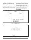
riaP
pirtSlanimreT
snoitangiseDsnoitangiseD
snoitangiseD
snoitangiseDsnoitangiseD
niP004T
rebmuNrebmuN
rebmuN
rebmuNrebmuN
remotsuC
84-JR84-JR
84-JR
84-JR84-JR
morF/oT
krowteN
RT,TT74,14
oT
remotsuC
)xR(
RRD,TRD51,58,7
morF
remotsuC
)xT(
TTD,RTD55,942,1
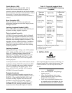
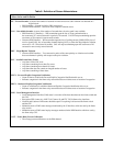
Table 4. Wiring Connections
Table 3. Compliance Codes
edoCtupnItuptuO
)CP(edoCrewoPFC
)CT(edoCnoitacinummoceleTX–
)CI(edoCnoitallatsnIA–
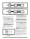
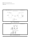
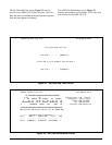
Connections are made using screwdown terminals on
the barrier strip located in the rear of a single mount
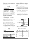
housing. Figure 3 describes the circuit card pinout.
Table 4 shows the wiring connections for the IDSL
OCU-R.
The housing should be wired as follows:
• Network pair to terminal strip TR and TT positions.
• To Customer and From Customer pairs through
customer 8-pin RJ-48 modular connector.
or
• To Customer (DRT, DRR) and From Customer
(DTR, DTT ) to designated terminal strip
positions.
• Local -48 Vdc power supplied to pins 17 (GND)
and 35 (-48 Vdc) of mounting is provided only
when the OCU-R is
not span-powered from the
2-wire IDSL loop.
Figure 3. Circuit Card Pin Assignments
Frame Ground
(TT)
-48 Vdc RET
(DTT)
(TR) (DTR)
(DRT)
IDSL OCU-R
15
(DRR)
11
35
17
27
5
From
Customer
To
Customer
To
Network
41 55
47 49
-48 Vdc PWR