


8 61220010L2-5, Issue 3 61220010L2-5C
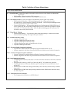
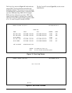
Table 8. Definition of Screen Abbreviations
Abbreviation and Definition
ES – Errored Seconds: A count of the number of seconds in which at least one code violation was detected on a
digital circuit.
• IDSL Interface ....Second in which a CRC error occurs.
• Customer DDS Interface....Second in which a bipolar violation occurs.
UAS – Unavailable Seconds: A count of the number of seconds that a circuit or path is not available.
• IDSL Interface (U-Interface) ....Will accumulate upon the loss of loop synchronization or
the occurrence of 7 errored seconds in a period of 20 seconds. UAS will stop accumulating upon the
occurrence of 30 consecutive non-errored seconds.
• Customer DDS Interface.... Will accumulate upon the loss of sealing current (LOOP OPEN), loss of
receive signal (LOS), loss of secondary channel framing (LOF), or when the illegal bipolar violation
error rate is >1E-3 for at least 10 seconds. UAS will stop accumulating upon the occurrence of 10
consecutive non-severely errored seconds.
BPV – Illegal Bipolar Violation
• Customer DDS Interface.... Two consecutive pulses of the same polarity or violation received that
does not alternate in polarity with respect to the prior violation.
INV – Invalid Frame Relay Frame
• Any frame with a CRC error.
• Any frame containing fewer than five octets.
• Any frame containing more than 8191 octets.
• Any frame that does not contain an integral number of octets.
• Any frame containing a frame abort.
FECN – Forward Explicit Congestion Notification
• Count of frames in which the Forward Explicit Congestion Notification bit was set.
• Indicates congestion in the frame relay network but does not isolate cause or location of congestion.
BECN – Backward Explicit Congestion Notification
• Count of valid frames in which the Backward Explicit Congestion Notification bit was set.
• Indicates congestion in the frame relay network but does not isolate cause or location of congestion.
LMI – Local Management Interface
• Local Management Interface (LMI) status is a monitor of the heart beat between the frame switch and
the CPE.
• Recognizes FRF (Annex A), ANSI T1.617 Annex D, and ITU T.933A frame relay interfaces.
• Network and Customer LMI counts should be equal if everything is ok between the frame switch
and the CPE.
• Maintains counts of LMI status messages monitored by the U-Interface, which are sent by the frame
relay switch.
• Maintains counts of LMI status inquiry messages monitored at the DDS Interface which are sent by
the frame relay CPE.
%UT – Frame Relay Percent Utilization
• The average percent utilization over the DS0 channel.