


761220010L2-5, Issue 361220010L2-5C
All existing latching loopbacks can also be disabled
by pressing the TEST or LBK pushbutton on the
U-BR1TE or remote unit, respectively.
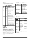
NOTE
The remote end test feature is only supported
when the upstream U-BR1TE is an ADTRAN
D4 or Series 5 U-BR1TE with DDS Loopback
capability. Other U-BR1TEs will ignore the
loopback command sent by pressing the IDSL
OCU-R LBK button.
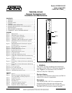
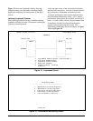
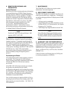
5. CONTROL PORT OPERATION
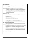
The IDSL OCU-R front panel DB-9 provides an
RS-232 interface for connection to a controlling
terminal. The pinout of the DB-9 is illustrated in
Figure 8.
NOTE
When conducting a Terminal Session, always
select VT100 mode prior to making the craft
connection.
The terminal interface operates at data rates from
1.2 kbps to 19.2 kbps. The asynchronous data format
is fixed at 8 data bits, no parity, and 1 stop bit. The
supported terminal type is VT100 or compatible.
NOTE
If using a personal computer (PC) with terminal
emulation capability, disable all power saving
programs. Otherwise, communication between
the PC and the IDSL OCU-R unit can be
disrupted, resulting in misplaced characters or
screen timeouts.
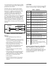
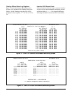
Operation
The T200 IDSL OCU-R is ready for synchronization
and operation upon insertion in an active shelf or
housing. Terminal sessions provide access to screen
menus for provisioning, monitoring, testing, or
obtaining performance history. Terminal session
screen access is available at any time during
operation. The screens shown in this practice identify
the main menu screens; subordinate screens are not
depicted. Abbreviations used in the screen diagrams
are detailed in Table 8.
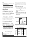
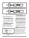
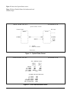
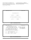
Figure 7. IDSL/DDS Remote End Initiated Loopback, Customer Loop
4-Wire
CPE Interface
IDSL
OCU-R
Push twice for IDSL OCU-R
Loopback
Local Loop
ASC 9Eh
U-BR1TE
Loopback
Pushbutton
Test
Set
ASC 9Eh
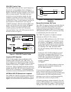
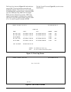
4-Wire
CPE Interface
IDSL
OCU-R
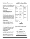
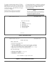
Push once for
U-BR1TE Loopback
Local Loop
ASC 9Eh
U-BR1TE
Loopback
Pushbutton
Test
Set
Figure 6. IDSL/DDS Remote End Initiated Loopback, Local Loop
Figure 8. RS-232 (DB-9) Cable Side Pin
Assignments
6
7
8
9
1
2
3
4
5
TXD (Transmit Data)
RXD (Receive Data)
SGN (Signal Ground)