


Total Access 3000/3010 4-Pair Line Power Unit Installation and Maintenance Practice
6 61181500L2-5B
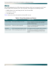
CAUTION
Installations in a CO or other controlled environment require heat
baffles.
CAUTION
Installations in remote locations require fans.
NOTE
A maximum of seven LPUs with a nominal load of about 0.3 amps
can currently be inserted into the Total Access 3000/3010 shelf.
This limitation is due in part to the 30 amp fuse used with the
Total Access 3000/3010 shelf and because the Total Access 3000/
3010 backplane traces that supply the –48 VDC current cannot
handle more than a consistent 20 amps.
To install the LPU, perform the following steps:
1. If present, remove the Access Module Blank (P/N 1181953L1) from the appropriate access
module slot of the Total Access 3000/3010 chassis.
2. Pull the ejector latch, located on the lower left-hand side of the LPU front panel, from its
closed position.
3. Hold the LPU by the front panel while supporting the bottom edge of the module with the
ejector latch opened to engage the chassis edge.
4. Align the module edges to fit in the lower and upper guide grooves for the access module
slot.
5. Slide the module into the access module slot. Simultaneous thumb pressure at the top
(above the
POWER LED) and at the bottom (below the electrostatic caution symbol) of the
module ensures that the module is firmly positioned against the backplane of the chassis.
6. Secure the LPU in place by pushing in on the ejector latch.
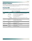
Upon installation, the LPU initiates a self-test. Once the power up self-test is completed, the
front panel LEDs reflect the true state of the hardware. For LED descriptions, refer to “Front
Panel LEDs” on page 9.