


Installation
61181500L2-5B 7
Wiring
WARNING
Disconnect power at the source and provision the service state as
Out of Service before making power connections.
Each LPU 96-pin edge connector inserts into a 96-pin backplane socket. The main edge
connector has pins for ground, alarms, provisioning, and card input power, plus output power
for the remote DSLAM. The daughter card has pins for ground and input power. Output power
is available on the 64-pin amphenol connectors on the Total Access 3000/3010 backplane.
The Total Access 3000/3010 chassis has eight 64-pin amphenols on the backplane. They are
labeled as follows:
• PAIR 1
• PAIR 2
• PAIR 3
• PAIR 4
• PAIR 5
• PAIR 6
• PAIR 7
• PAIR 8
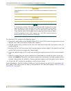
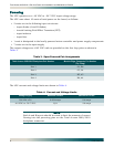
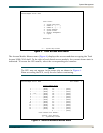
As shown in Table 2, if the LPU inserts into slots 1 and 2 of the Total Access 3000/3010, the
power pairs appear at loop connections 1 through 4 of slot 1. If the LPU inserts into slots 9
and 10, the power pairs appear at loop connections 1 through 4 of slot 9. If the LPU inserts
into slots 20 and 21, the power pairs appear at loop connections 1 through 4 of slot 20, etc.
for a maximum allowable number of LPUs based on the Total Access 3000/3010 amperage
input limit.
Table 2. Wiring Example
LPU Slots Used Slot Where Power
Pairs Appear
1 1, 2 1
2 9, 10 9
3 20, 21 20